Supercharge Your Innovation With Domain-Expert AI Agents!

Liquid discharge apparatus

a technology of liquid discharge apparatus and liquid discharge, which is applied in the field of liquid discharge apparatus, can solve the problems of foreign matter coming into contact with the head, damage to the head, and becoming more difficult to detect foreign matter on the medium, so as to improve the accuracy of detection of foreign matter

Active Publication Date: 2016-10-25
SEIKO EPSON CORP
View PDF5 Cites 0 Cited by
  • Summary
  • Abstract
  • Description
  • Claims
  • Application Information

AI Technical Summary

Benefits of technology

The present invention provides a technique to improve the accuracy of detecting foreign matter on a medium. This is achieved by curbing the formation of a clearance between a movable roller and the medium supported by a support member. This is achieved by inclining the movable roller relative to the support member, even if the surface of the support member becomes deformed. The inclination of the movable roller makes it possible to press it against the support member, reducing any clearance between them. The invention also involves using a hardness of 80 degrees or more on the peripheral surface where the movable roller comes in contact with the medium to prevent deformation. Most importantly, this technique improves the accuracy of detecting a foreign matter even if there is thermal deformation of the support member.

Problems solved by technology

At this time, if a foreign matter is present on the medium, the foreign matter may end up coming into contact with the head and damaging the head.
In a configuration for thus detecting a foreign matter on a medium on the basis of displacement of a movable roller nipping the medium with a support member on the other side, it becomes more difficult to detect the foreign matter on the medium if there is a vacant clearance between the medium and the movable roller.
However, there are instances where, for example, the surface of the support member ends up being inclined due to causes such as thermal deformation, creating a vacant clearance between the movable roller and the medium supported by the support member, and lowering the accuracy of detection of a foreign matter present on the medium.
Namely, with such a liquid discharge apparatus, the heating of the liquid is likely to cause the support member to undergo thermal deformation.

Method used


Image

  • Liquid discharge apparatus
  • Liquid discharge apparatus
  • Liquid discharge apparatus

Examples


Embodiment Construction

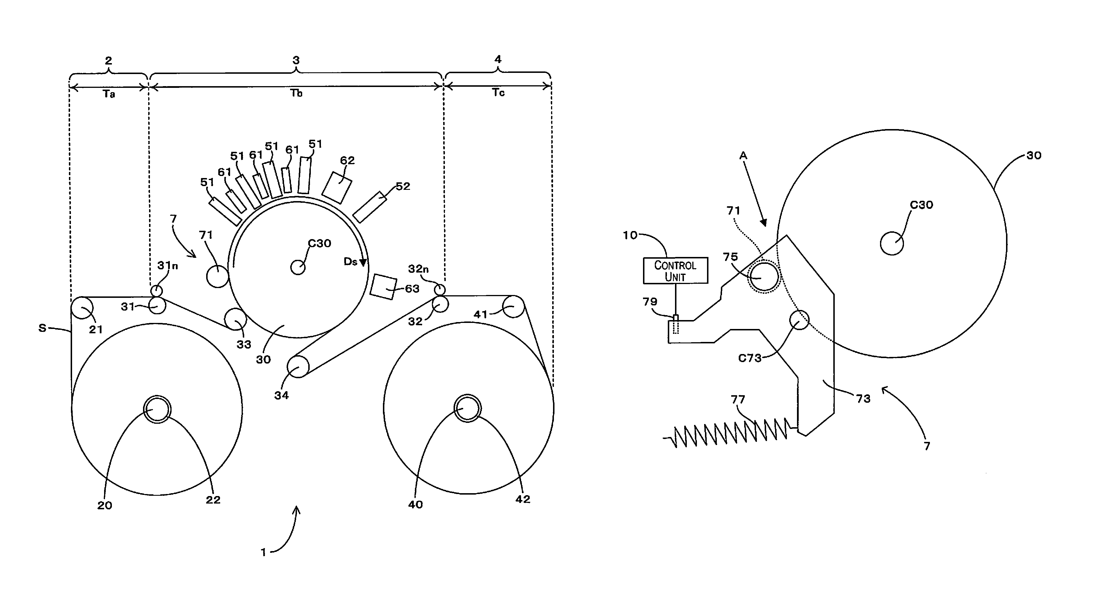
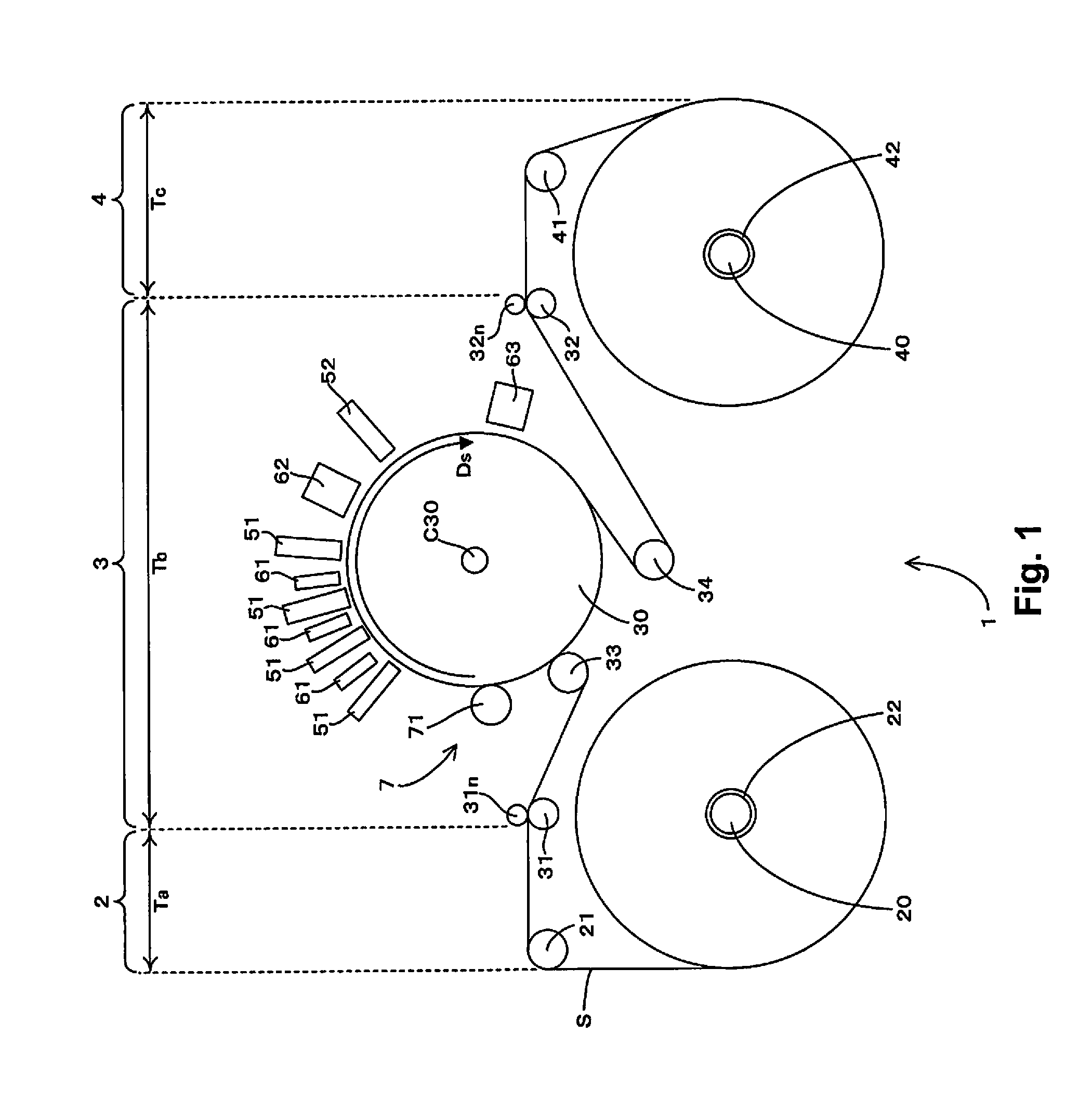
[0024]FIG. 1 is a front view schematically illustrating the configuration of a printer to which the present invention has been applied. As illustrated in FIG. 1, in a printer 1, a single web S of which both ends have been wound up in the shape of a roll around a feed-out spindle 20 and a take-up spindle 40 is extended in a tensioned state along a conveyance path, and the web S undergoes image recording while also being conveyed in a direction of conveyance Ds going from the feed-out spindle 20 toward the take-up spindle 40. Such webs S are broadly divided into being either paper-based or film-based. As specific examples, paper-based includes high-quality paper, cast paper, art paper, coated paper, and the like, while film-based includes synthetic paper, polyethylene terephthalate (PET) film, polypropylene (PP) film, and the like. As an overview, the printer 1 is provided with: a feed-out part 2 (feed-out region) for feeding the web S out from the feed-out spindle 20; a process part ...


PUM


Abstract

The liquid discharge apparatus includes a support member supporting a medium while rotating, a head facing the support member and discharging a liquid, a conveyance part conveying a medium between the support member and the head, and a foreign matter detection unit detecting a foreign matter heading toward between the support member and the head in association with the conveyance of the medium. The foreign matter detection unit has a movable roller that faces the support member upstream relative to the head in a conveyance direction of the medium, and nips the medium between the support member and the movable roller, a rotational support member rotatably supporting the movable roller to allow inclination of the movable roller relative to a rotational axis direction, which is a center of rotation of the support member, and a retention member movably retaining the rotational support member in a direction toward the support member.

Description

CROSS-REFERENCE TO RELATED APPLICATIONS[0001]This application claims priority to Japanese Patent Application No. 2015-029489 filed on Feb. 18, 2015. The entire disclosure of Japanese Patent Application No. 2015-029489 is hereby incorporated herein by reference.BACKGROUND[0002]1. Technical Field[0003]The present invention relates to a technique for detecting a foreign matter present on a medium in a liquid discharge apparatus for discharging a liquid from a head onto a medium supported by a support member.[0004]2. Related Art[0005]There is a known printing apparatus provided with a support member for supporting a medium and a head that faces the support member, printing being performed onto the medium by the discharging of ink from the head onto the medium supported on the support member. Such a printing apparatus executes printing onto the medium while also conveying the medium between the support member and the head. At this time, if a foreign matter is present on the medium, the f...

Claims


Application Information

Patent Timeline
Patent Type & Authority Patents(United States)
IPC IPC(8): B41J29/393B41J25/308B41J15/00B41J2/165B41J13/02B41J11/00B41J11/20B41J11/24B41J13/00B41J2/045B41J25/312B41J25/316B41J13/036
CPCB41J15/00B41J2/04556B41J2/165B41J11/005B41J11/0095B41J11/20B41J11/24B41J13/0027B41J13/0063B41J13/02B41J13/025B41J13/036B41J25/308B41J25/3084B41J25/3088B41J25/312B41J25/316G01N21/89B41J11/0021
Inventor TOYAMA, HIROSHISHIIYA, TOMOYUKI
Owner SEIKO EPSON CORP
Features
  • R&D
  • Intellectual Property
  • Life Sciences
  • Materials
  • Tech Scout
  • Unparalleled Data Quality
  • Higher Quality Content
  • 60% Fewer Hallucinations
Learn More