Multi-charge munitions, incorporating hole-boring charge assemblies

a technology of charge assembly and munitions, which is applied in the direction of explosive charges, weapons, fall bombs, etc., can solve the problems of affecting the weight of known hollow charges cannot meet all requirements, and the maximum damage to the target is increased, so as to facilitate the emplacement of follow-through charges

Active Publication Date: 2016-10-25
QINETIQ LTD
View PDF16 Cites 9 Cited by
  • Summary
  • Abstract
  • Description
  • Claims
  • Application Information

AI Technical Summary

Benefits of technology

[0011]It is one of object of the present invention to provide a multi-charge munition incorporating a hole-boring charge assembly which can more adequately facilitate the emplacement of a follow-through charge within a target.

Problems solved by technology

The materials of construction of these targets are typically strong in compression and yet weak in tension, as exemplified by most forms of concrete.
However, such known hollow charges fail to fulfil all the requirements for a variety of reasons.
However the resulting holes bored in the target material tend to be narrow and tapered and so are not suitable for the subsequent emplacement of a blasting charge therein.
The diameter of the hole can be increased by increasing the diameter of the hollow charge, but the corresponding increase in weight of the hollow charge is undesirable and furthermore the increase in target penetration in targets of finite thickness such as concrete walls, roads and runways may cause the secondary, follow-through charge to be emplaced beyond the depth at which it can cause maximum damage to that target.
However, the shorter lengths and lower kinetic energies of these penetrators result in a significant reduction in performance especially against concrete targets, necessitating an undesirably large charge mass in order to excavate a hole of sufficient volume to permit emplacement of the secondary, follow-through charge to an optimum depth.
The need for a relatively large mass of explosive in the hole-boring hollow charge reduces the weight of explosive which can be used in the secondary, follow-through charge for a given overall weight of multi-charge munition, and when the hole-boring charge is detonated consequently gives rise to excessively large forces on the follow-through charge which may damage the follow-through charge and / or its fuzing system.

Method used


Image

  • Multi-charge munitions, incorporating hole-boring charge assemblies
  • Multi-charge munitions, incorporating hole-boring charge assemblies
  • Multi-charge munitions, incorporating hole-boring charge assemblies

Examples


Embodiment Construction

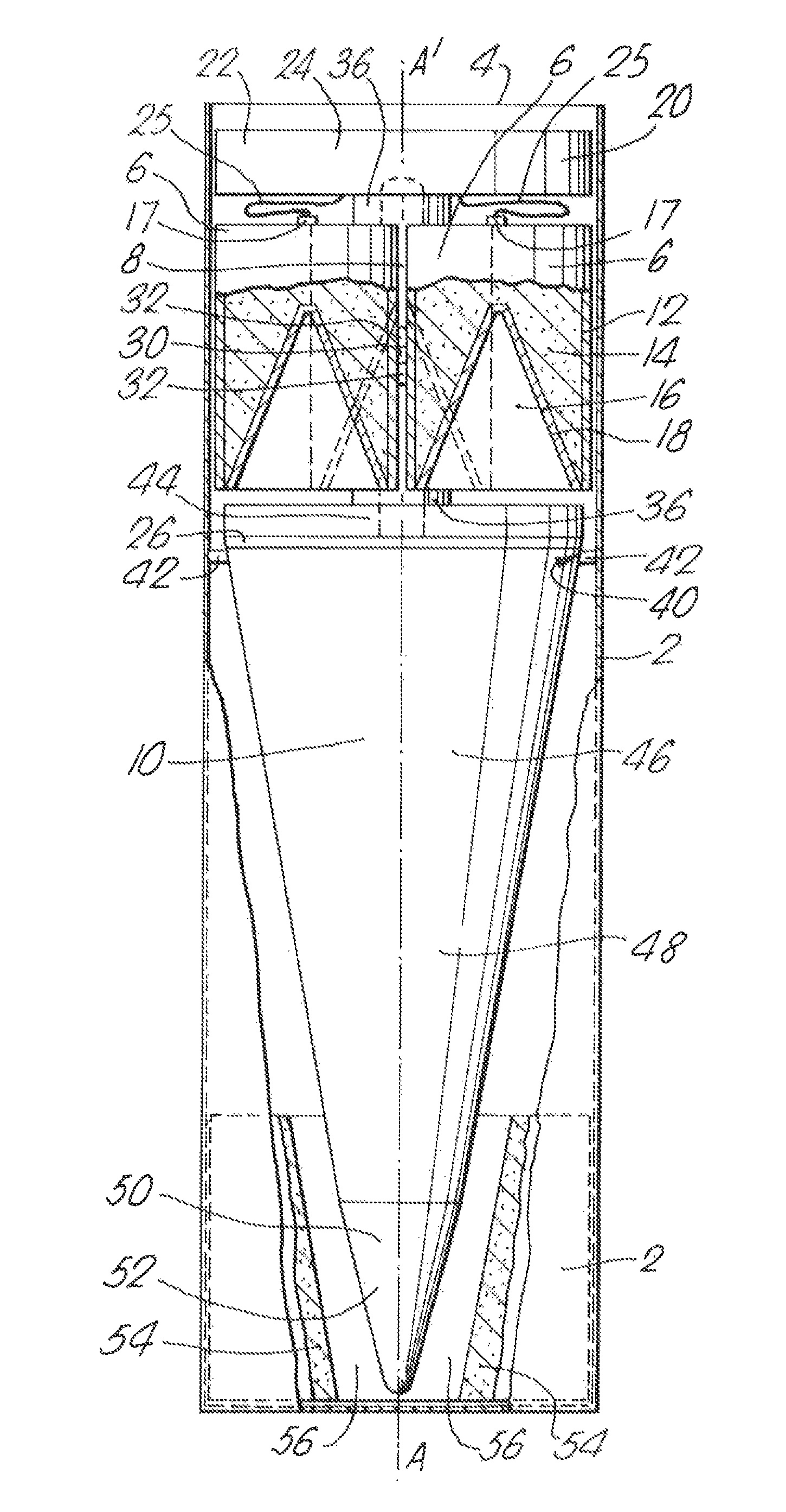
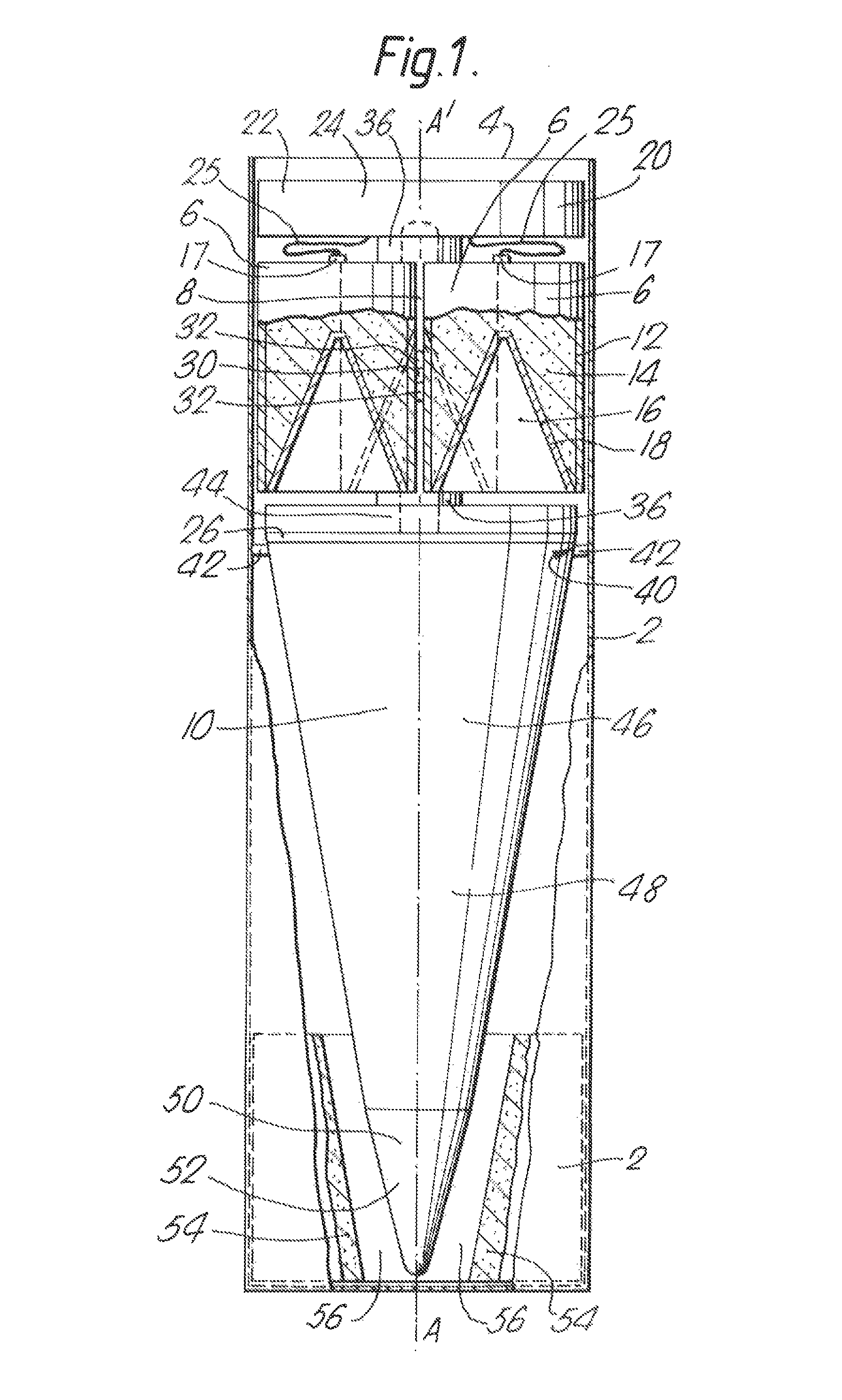
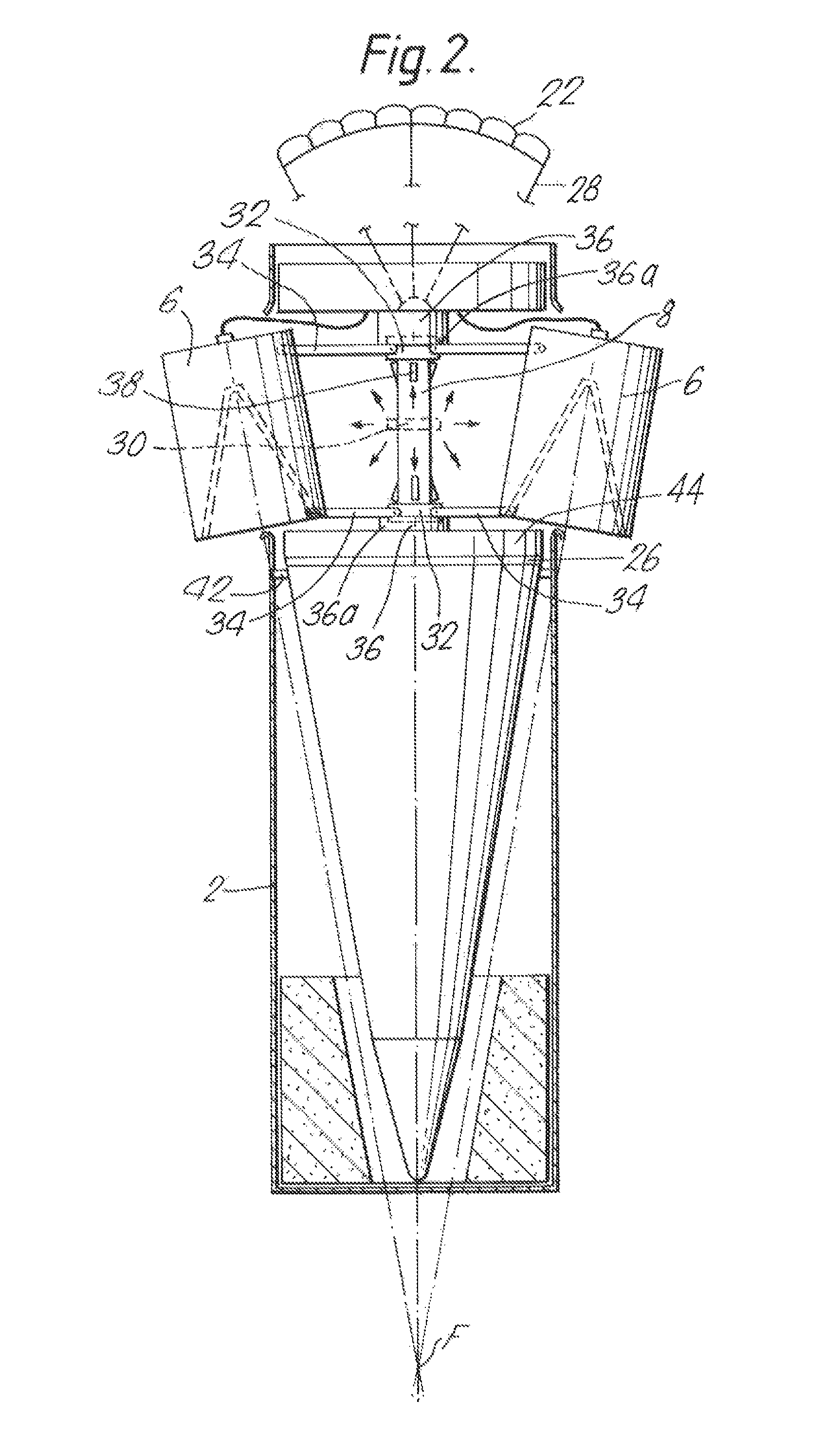
[0043]Referring first to the embodiment illustrated in FIGS. 1 and 2, there is illustrated in FIG. 1 a reverse follow-through submunition with a longitudinal fore-and-aft axis AA′ consisting of a frangible cylindrical canister 2, with an open rear end 4, shown partly cut-away to reveal its contents. These contents consist primarily of three primary hollow charge munitions 6 positioned in a closely packed, parallel configuration about a support shaft 8 behind a conical encased secondary munition 10. The view of one of the primary munitions 6 is obscured by the other two and so its position is shown in broken outline. The two primary munitions 6 shown in solid relief are shown part-sectional, and each consists of a cylindrical casing 12 open at its forward end and containing a hole-boring shaped charge 14 of high explosive having a right-conical recess 16 in its forward face, and a rearward, axially-positioned detonator 17. The recess is lined with a low density liner 18 of non-explos...


PUM


Abstract

Multi-charge munition suitable for defeating a concrete target consists of a detonatable array of hollow primary charges (14) of explosive supported laterally of a line of target penetration on which is disposed a secondary explosive charge (48). Simultaneous detonation of the primary charges in the array causes jet penetrators to be projected together towards the target which produce wide boreholes in concrete suitable for the subsequent emplacement and detonation of the secondary charge. The munition may be an aerially-deliverable bomb or submunition.In one preferred embodiment, the primary charges (14) are positioned in a convergent configuration behind a forwardly-tapered secondary charge (48). Detonation of the primary charges projects penetrators forwardly passed the sides of the secondary charge and thrusts the secondary charge into the borehole produced in the target by the penetrators.

Description

BACKGROUND OF THE INVENTION[0001]1. Field of the Invention[0002]This invention relates to multi-charge munitions incorporating hole boring charge assemblies, in particular hole-boring charge assemblies capable of penetrating concrete targets.[0003]2. Discussion of Prior Art[0004]It is known that the attack, disruption, and destruction of fixed targets such as airfield runways, shelters, bunkers, bridges, roadways, railway marshalling yards and dockyards may be effected by first emplacing and then detonating relatively small quantities of high explosive within or under the target. The materials of construction of these targets are typically strong in compression and yet weak in tension, as exemplified by most forms of concrete. Such emplacement exploits both the inherent confining effect of the target material on the charge of emplaced explosive and the tensile weakness of the target material, and futhermore enhances the transmission of energy from the detonated explosive into the im...

Claims


Application Information

Patent Timeline
Patent Type & Authority Patents(United States)
IPC IPC(8): F42B12/10F42B12/16F42B12/12F42B12/14F42B1/032F42B1/028F42B25/00F42B3/08
CPCF42B12/16F42B1/028F42B12/10F42B12/14F42B12/12F42B1/032F42B25/00F42B3/08
Inventor POWELL, KEVIN MARKEVANS, EDWARD
Owner QINETIQ LTD
Why Eureka
Try Eureka