Optical sensor for contactless pressure measurements

a technology of optical sensors and pressure measurements, applied in the field of optical sensors, can solve the problems of less reliable, more sensitive mechanical vibration of “interferometric” sensors, and even more expensive of “interferometric” sensors, and achieve the effect of increasing reliability

Active Publication Date: 2016-10-25
LASER POINT SRL
View PDF16 Cites 1 Cited by
  • Summary
  • Abstract
  • Description
  • Claims
  • Application Information

AI Technical Summary

Benefits of technology

[0016]In view of the state of the art, it is an object of the present to provide an optical sensor for contactless pressure measurements which is more efficacious with respect to the known ones and has increased reliability with the possibility to use it in harsh industrial environment.
[0024]Said optical sensor is of the “Intensity modulated” optical sensor type and it is based on an optimized optical design to improve SNR and sensitivity of the sensor and on a fabrication method to allow this optical sensor to be used in harsh industrial environment where very high operating temperatures are reached.
[0025]The use of the optical sensor with said improved sensitivity and increased Signal to Noise Ratio at the receiver side, allows the easier detection of very small displacement of the pressure sensing diaphragm, when high pressure range have to be measured using a thicker diaphragm needed to avoid its break under the effect of the high pressure.
[0026]The use of optical sensor for pressure measurement for a contactless optical measurement of pressure, means that no direct mechanical contact of the movable pressure sensing diaphragm with other parts takes place inside the sensor head (in contrast with the case of piezo-resistive, and piezoelectric sensors where a direct contact between the detector chip and the movable with pressure diaphragm is needed to generate the output voltage inside the sensor head). This “contactless” feature, together with the ability of said optical sensor to be used in harsh industrial conditions where high process temperatures are reached and the ability of said optical sensor to be used in harsh industrial conditions where high pressure value are reached, allows said optical sensor to be used in automotive field for pressure measurement in cylinder combustion chamber; as matter of fact, considering the very high value of revolutions per minute of the engine, pressure measurement performed in a “contactless” way is mandatory to increase the sensor robustness avoiding the break of the sensor due to attrition between the movable deformable diaphragm and other sensor parts as in the case of piezoelectric and piezo-resistive sensors. On the other side, the very high temperatures and pressure reached in the combustion chamber (700° C. / 200 Bar) requires the optical sensor to be implemented with a robust optical design based on materials which are compatible with so high temperatures and on a thick enough diaphragm able to resist to the high pressure range and to fast pressure changes.
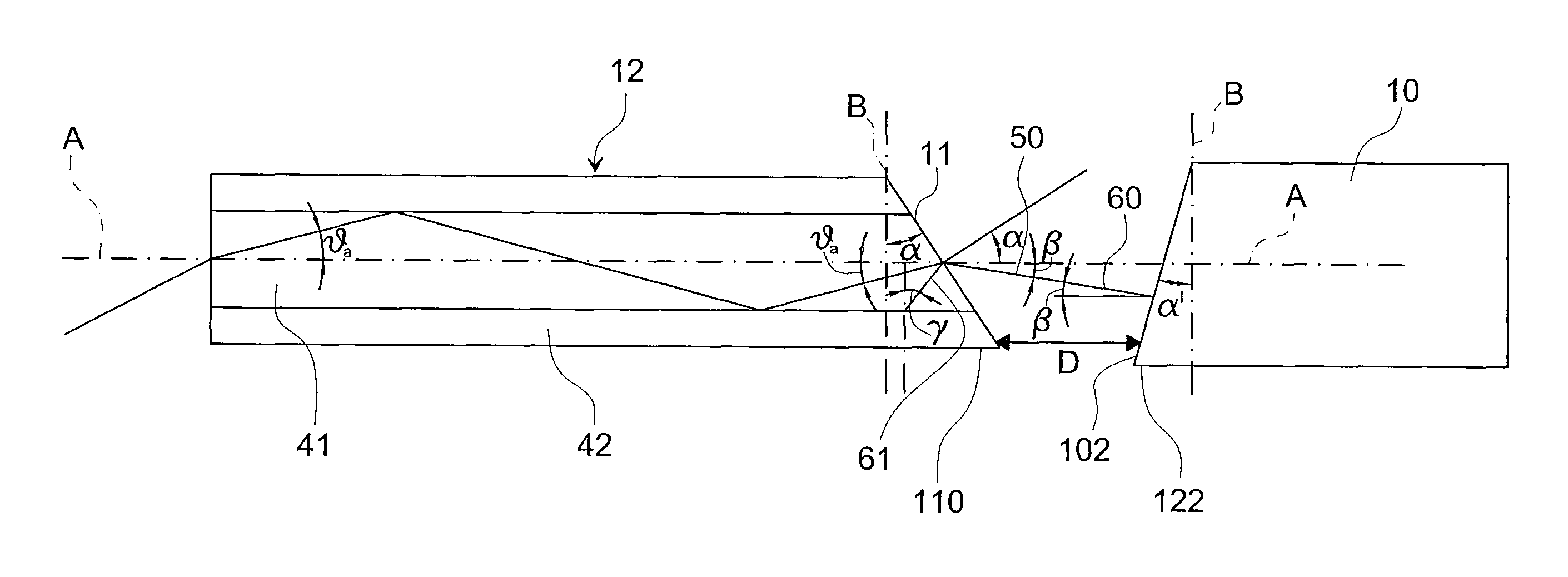
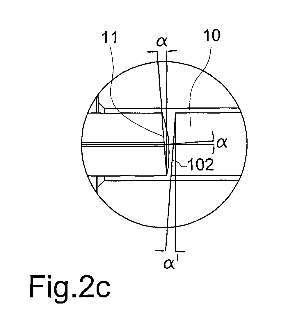
[0029]In the optical sensor according to the present invention, the end surface of the waveguide means, preferably the optic fiber, used inside the sensor head, is angled cut with an optimized angle able to reduce the optical noise level at the receiver side coming from Fresnel back reflection which always occurs at the fiber end surface; as matter of fact, Fresnel reflection happens always when a light beam reaches an optical interface where a refractive index mismatch takes place, as in the case of fiber end surface due to the big difference between fiber glass and air refractive index. The angled cut fiber end surface used in the present invention is optimized in such a way that the reflected light at the fiber end surface due to intrinsic Fresnel reflection is not driven back anymore by the optical fiber itself; this happens when the reflected rays from Fresnel reflection have an incident angle inside the optic fiber, that is the angle wherein the reflected light beam incises the interface between fiber core and cladding, less than the critical angle of the used fiber. Reflected light due to Fresnel reflection is main responsible of the optical noise level increase at the receiver side which, in turn, dramatically degrades the SNR of the optical sensor. Using an angled cut fiber end surface, the direction of the escaping optical beam is deflected away from the optical fiber axes according with the Snell refraction law; in order to maximize the intensity of reflected light collected by the angled cut fiber end surface, the reflective surface of the pedestal has to be properly tilted to reflect the incident optical beam back to the same point where it escaped from the fiber itself.
[0030]Moreover, the use of the angled cut fiber end surface allows to remove the negative effect on the receiver performance of Fresnel back reflection without using any antireflective coating materials, which are not compatible with high temperature operating conditions; this makes the sensor based on the present invention, well suitable for the use in harsh industrial environment where very high temperatures are reached,

Problems solved by technology

“Interferometric” sensors have the advantage to measure pressure with an higher resolution than the “Intensity modulated” ones but on the other side, “Interferometric” sensors are more sensitive to mechanical vibrations (often present in industrial environment) and less reliable due to the use of more complicated optical design related to the interferometers.
The use of interferometer and the need of a coherent LASER source makes the “Interferometric” sensors even more expensive than the rocky and robust optical “Intensity modulated” sensor where low cost not-coherent LED source may be used.
Even if both kinds of these sensors are widely used in industrial environment where harsh conditions are reached, many of the previous listed advantages are not applicable anymore for this kind of sensors; specifically, this sensor needs a mechanical contact between the transducer chip and the pressure sensing diaphragm.
Even if the transducer chip is typically shielded in a metal enclosure avoiding EMI problems, the electronics needed for detection and signal conditioning can still suffer of EMI problems, because it has to be still close enough to the transducer chip box to avoid degradation of small amplitude signal using long and expensive electrical cables.
Optical sensor design based on multiple fibers or ribbon is more complicated, more difficult to manufacture with a reliable mass production process and even more complicated to be integrated in smaller size than a single fiber based optical sensor solution.
The prior art optical sensors cannot be used in industrial environment where harsh conditions due to extremely high process temperatures are reached; in fact, this is due to the limited temperature operating range of the available glues and materials needed to optimize the optical design (i.e. coating materials used as anti-reflective layer for refractive index matching to reduce optical back reflections at the fiber optic termination) and to package the optical elements inside the sensor itself (for example the glue materials used to fix optical elements as mirrors, lens, fiber, etc.).

Method used


Image

  • Optical sensor for contactless pressure measurements
  • Optical sensor for contactless pressure measurements
  • Optical sensor for contactless pressure measurements

Examples


Embodiment Construction

[0037]An optical sensor for pressure measurements according to the present invention is shown in FIGS. 1-3. Specifically the optical sensor comprises (FIG. 1), an optical source 1, for example a LED or a LASER source, which is connected by means of a fiber to an optical isolator 2 and the optical isolator is further optically connected to an input port PORT 1 of a directional optical coupler 3. The optical isolator 2 is needed to avoid that the light back reflected reaches the optical source possibly producing some optical instability of the source itself. The directional optical coupler 3 comprises another input port PORT 2 which is optically connected by means of a fiber with a receiver 5, for example a PIN or an APD; the output port PORT 3 of the directional optical coupler 3 is optically connected to the input of a waveguide means 4, for example a single mode or multimode optical fiber. The length of this waveguide means 4 may be done long enough from few meters to some kilomete...


PUM

PropertyMeasurementUnit
angleaaaaaaaaaa
angleaaaaaaaaaa
displacementaaaaaaaaaa

Abstract

An optical sensor for pressure measurements comprises a sensor head including: a diaphragm having a first surface in contact with a fluid of which the pressure has to be measured and a second surface opposite to the first surface, a body with a tubular cavity, means arranged inside the tubular cavity, associated with the second surface of the diaphragm and movable longitudinally inside said tubular cavity in response to deformation of the diaphragm, said means including a reflective surface, an end part of waveguide means arranged inside the tubular cavity and having the end surface faced to and not in contact with the reflective surface of said means, said waveguide means being connected to a light source and a receiver respectively to send to said means the light beam deriving from the light source and to collect at the receiver the light beam reflected from the reflective surface.

Description

BACKGROUND OF THE INVENTION[0001]Optical sensors for pressure measurement may be generally divided into two main different families according to the different approach used to measure the pressure parameter: “Interferometric” and “Intensity modulated” optical sensors. In the “Interferometric” optical sensors, the pressure is measured by the phase change between the incoming optical probe beam and the out-coming from an optical pressure sensing element (using Bragg, Fabry-Perot, Michelson, Mach-Zehnder interferometers). In the “Intensity modulated” optical sensors, the pressure is directly measured by the intensity change between the incoming optical probe beam and the out-coming one from an optical pressure sensing element (typically a reflective surface of a pressure sensing diaphragm) In the “Intensity modulated” optical sensors, fiber optic is used to drive incoming optical beam in front of the pressure sensing reflective diaphragm and to collect the light beam reflected by the d...

Claims


Application Information

Patent Timeline
Patent Type & Authority Patents(United States)
IPC IPC(8): G01L9/00G01L7/00G01L7/08G01L11/02
CPCG01L7/086G01L11/02
Inventor BRINCIOTTI, ANDREACIBINETTO, LUCIO
Owner LASER POINT SRL
Why Eureka
Try Eureka