Mixer drum driving device

a driving device and mixer technology, applied in the direction of clay preparation equipment, mechanical equipment, transportation and packaging, etc., can solve the problems of deterioration of the mountability of the mixer drum onto the chassis, enlargement of the motor and a power supply, and heavy mixer trucks, so as to achieve the effect of not reducing the transportation efficiency

Inactive Publication Date: 2016-11-01
KYB CORP
View PDF13 Cites 5 Cited by
  • Summary
  • Abstract
  • Description
  • Claims
  • Application Information

AI Technical Summary

Benefits of technology

[0011]An object of the present invention is to provide a mixer drum driving device capable of driving a mixer drum by a motor without reducing transportation efficiency.

Problems solved by technology

Thus, an inverter necessary to drive the motor is necessary and, in addition, a high-output motor needs to be used, leading to the enlargement of the motor and a power supply.
Since this increases the number of components for driving the motor and enlarges the motor, the power supply necessary to drive the motor and other components, mountability of the mixer drum onto a chassis is deteriorated and the mixer truck becomes heavier.
Thus, the load capacity of the mixer drum has to be reduced and the amount of transportable fresh concrete decreases, thereby deteriorating transportation efficiency.
Further, since transportation efficiency is deteriorated, the amount of fuel consumption increases by that much.

Method used


Image

  • Mixer drum driving device
  • Mixer drum driving device
  • Mixer drum driving device

Examples


Embodiment Construction

[0017]Hereinafter, an embodiment of the present invention is described with reference to the drawings.

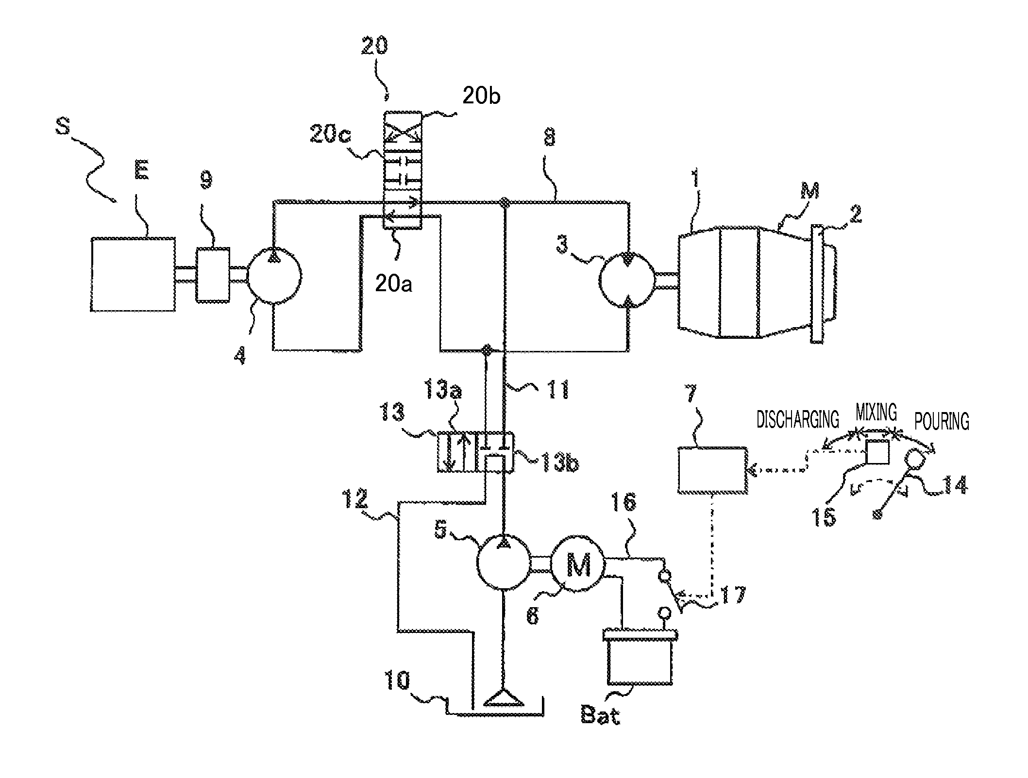
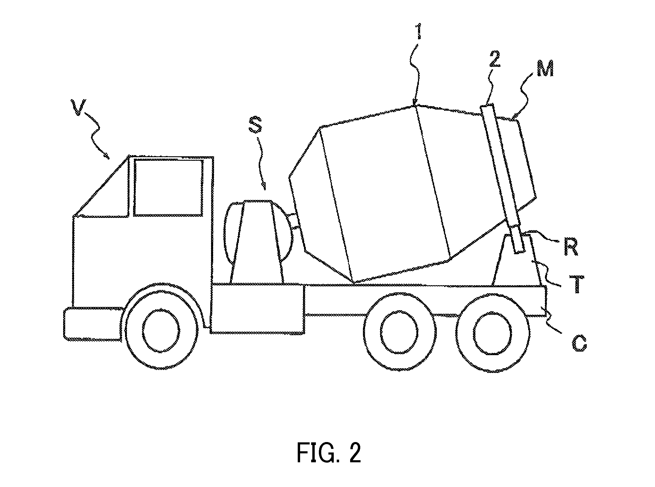
[0018]As shown in FIG. 1 and FIG. 3, a mixer drum driving device S in the present embodiment includes a mixer drum M rotatably mounted on a chassis C of a mixer truck V, a hydraulic motor 3 for driving and rotating the mixer drum M, a hydraulic pump 4 for supplying pressure oil to the hydraulic motor 3 by being driven by the power of an engine E of the mixer truck V, an auxiliary hydraulic pump 5 capable of supplying pressure oil to the hydraulic motor 3 independently of the hydraulic pump 4 to rotate the mixer drum M for mixing, a direct-current brush motor 6 for driving and rotating the auxiliary hydraulic pump 5 and a controller 7 for controlling the direct-current brush motor 6.

[0019]The mixer truck V includes legs T mounted on the chassis C and a pair of rollers R, R rotatably equipped in the legs T and carries the mixer drum M and the hydraulic motor 3, the hydraulic pump 4, t...


PUM

PropertyMeasurementUnit
pressureaaaaaaaaaa
poweraaaaaaaaaa
rotation speedaaaaaaaaaa

Abstract

A mixer drum driving device includes a mixer drum, a hydraulic motor, a hydraulic pump, an auxiliary hydraulic pump for rotating the mixer drum for mixing by supplying pressure oil to the hydraulic motor independently of the hydraulic pump, and a direct-current brush motor for driving and rotating the auxiliary hydraulic pump. In the case of rotating the mixer drum for mixing, the mixer drum is driven and rotated by driving only the auxiliary hydraulic pump by the direct-current brush motor.

Description

RELATED APPLICATIONS[0001]The present application is a National Phase of International Application Number PCT / JP2012 / 056684, filed Mar. 15, 2012, and claims priority from Japanese Application Number 2011-065506, filed Mar. 24, 2011.TECHNICAL FIELD[0002]The present invention relates to a mixer drum driving device.BACKGROUND ART[0003]A mixer truck carries mortar, ready-mixed concrete and the like (hereinafter, referred to as “fresh concrete”) in a mixer drum rotatably mounted on a chassis and transports these from a fresh concrete factory to a construction site.[0004]The mixer truck sets the mixer drum constantly in positive rotation to prevent quality degradation and solidification of the fresh concrete in transporting the fresh concrete. By the positive rotation of the mixer drum, a plurality of spiral blades mounted in the mixer drum constantly keeps mixing the fresh concrete. Further, the mixer truck can discharge the fresh concrete in the mixer drum by setting the mixer drum in n...

Claims


Application Information

Patent Timeline
Patent Type & Authority Patents(United States)
IPC IPC(8): B28C5/18B28C5/42F16H61/44B01F29/60
CPCB28C5/18B28C5/4213F16H61/44
Inventor TAKAHASHI, YOSHIMITSUTANAKA, KAZUNORI
Owner KYB CORP
Why Eureka
Try Eureka