Leveling device for laying tiles or the like

a leveling device and tile technology, applied in the construction industry, can solve the problems of not only hardly ever ensuring optimal, not only operating time-consuming, and requiring great skill, and achieve the effect of substantially coplanar surface and optimizing laying operation

Active Publication Date: 2016-11-01
PROFILITEC S P A SOCIO UNICO
View PDF20 Cites 20 Cited by
  • Summary
  • Abstract
  • Description
  • Claims
  • Application Information

AI Technical Summary

Benefits of technology

[0015]An object of the present invention is to at least partially overcome the above mentioned drawbacks by providing a leveling device for laying tiles or the like, which allows optimizing the laying operation and obtaining a substantially coplanar surface.
[0016]Another object of the present invention is to provide a leveling device that is easy to use and which allows, therefore, an easy adjustment of the arrangement of the tiles.
[0017]A further object is providing a device that allows an easy and safe removal from the tiled surface.
[0018]Another object is providing a device that allows maintaining low laying costs by enabling the recycling of most of the its components.
[0025]Advantageously, the use of the knob is simplified, since it is sufficient to set up the two half-shells to embrace the projecting element and subsequently to bring the cap until it surrounds them.
[0026]After solidification of the glue, the recovery of the knob is also advantageously simplified. It is sufficient, in fact, to cause the detachment from the base of the projecting element with the knob and then remove the blocking tie-rod from the cap. The two half-shells that compose the blocking tie-rod will then be free to separate by releasing the projecting element. The blocking tie-rod and the cap are therefore reusable.

Problems solved by technology

It is evident that such approach is not only operationally time-consuming, but also requires great skill and hardly ever ensures optimal results.
Generally, in fact, the tiles laid in this manner are not perfectly coplanar, not only because of the laying technique, but also because the solidification of the adhesive material may induce small movements that causes a loss of planarity.
However, this embodiment is expensive because a different tie-rod for each different tile thickness must be provided.
Furthermore, the detachment of the projecting element is not always easy.
The knob can also be recovered, but this can only occur by removing the remaining part of the projecting element and this is not always easily achievable.
In fact, this operation can only be performed from the detachment side of the projecting element from the base and the portion protruding from the knob could be particularly low.
Another drawback is that the pressure adjustment is not very easy since it is only possible to increase pressure and not to decrease it due to the interaction between the rack and the knob.
However, the recovery of the knob remains difficult because the installer is forced to unscrew from the knob the projecting element detached from the base.
Since typically the number of such devices is particularly high in use, it is evident that the operation is particularly costly in terms of both execution time and physical energy.

Method used


Image

  • Leveling device for laying tiles or the like
  • Leveling device for laying tiles or the like
  • Leveling device for laying tiles or the like

Examples


Embodiment Construction

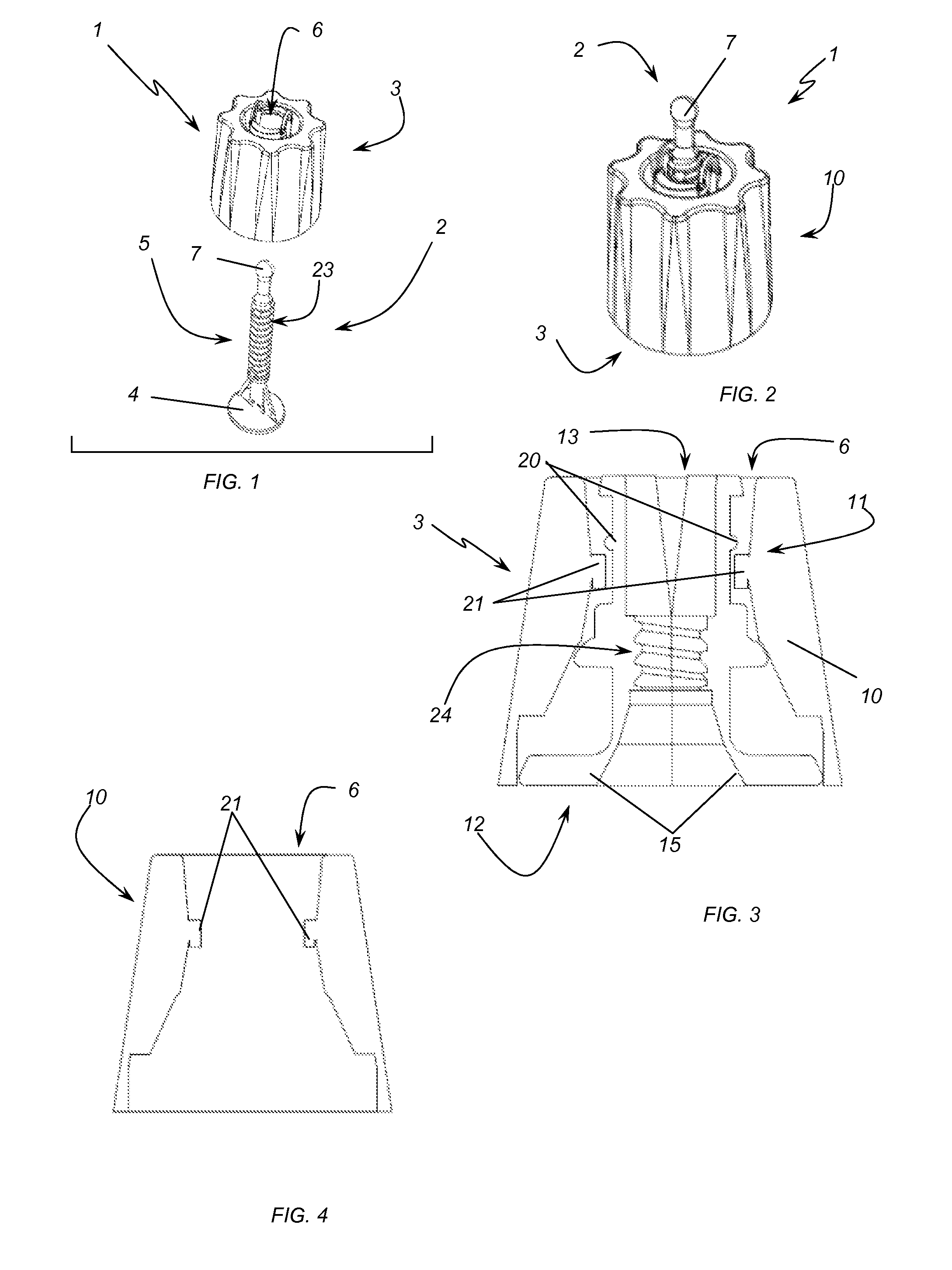
[0035]With reference to the figures, and in particular to FIGS. 1 and 2, an embodiment of a leveling device 1 according to the invention for laying tiles is described herein.

[0036]The device 1 comprises, like similar known devices, a tie-rod 2 and a knob 3.

[0037]In particular, the tie-rod 2 comprises a support base 4 to be disposed over an adhesive and to receive and support the edge portions of the tiles. It also comprises a projecting element 5 from the base 4 susceptible to be arranged into the junctions between adjacent tiles that rest on the base 4.

[0038]With regard to the knob 3, it can be coupled to the projecting element 5 and it has a pass-through hole 6 for the output of the free end 7 of the projecting element 5. As it is known, the knob 3 forces at least one portion of the edge of adjacent tiles against the base 4 to level the tiles being laid.

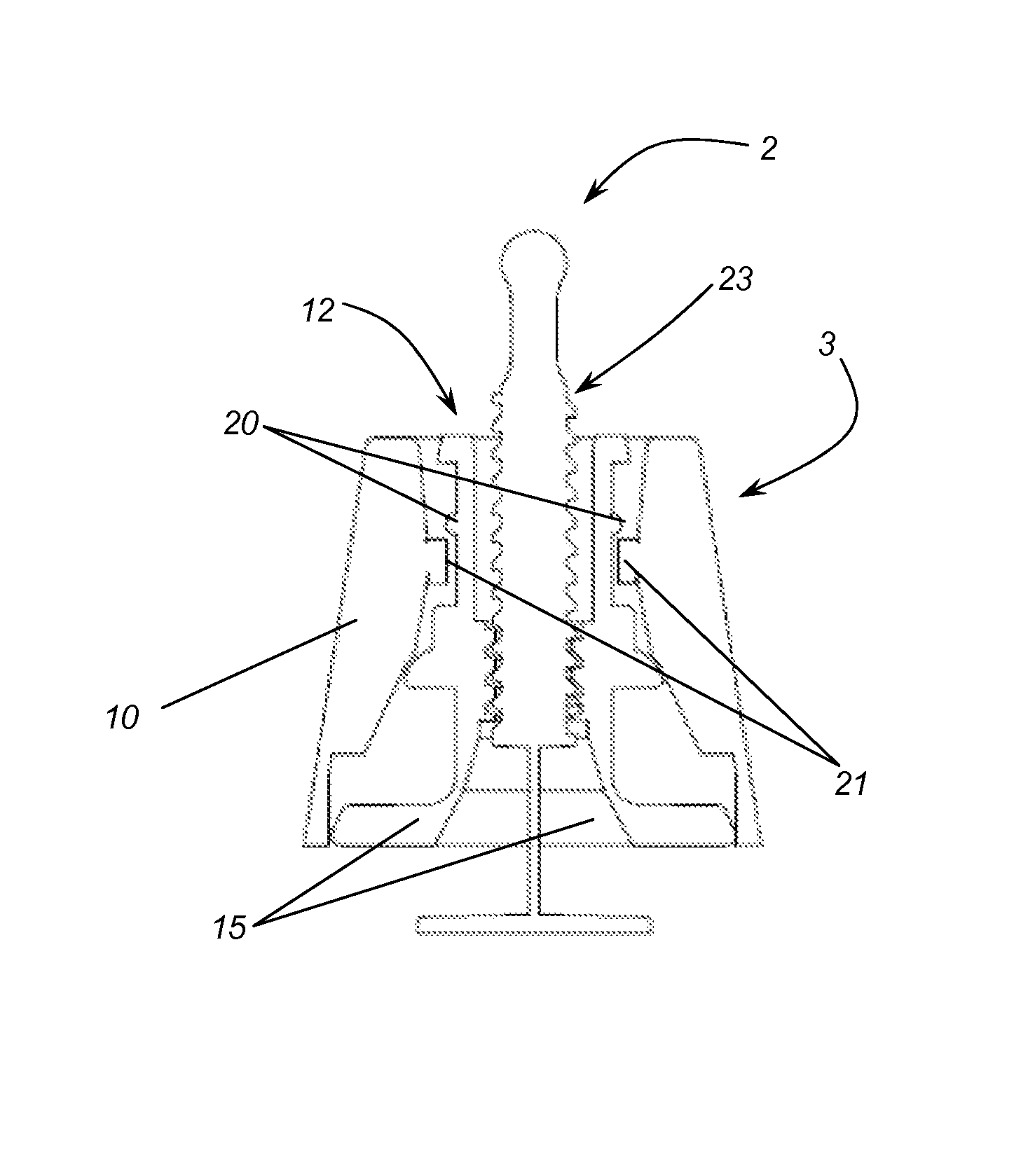
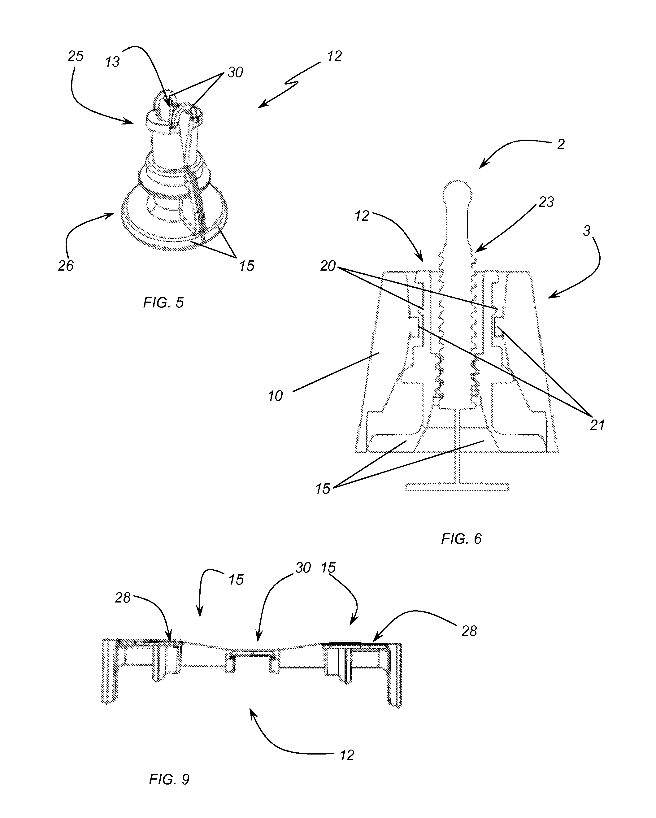
[0039]According to an aspect of the invention, the knob 3 comprises, as it can be observed in the details of FIGS. 3 and 4, a cap...


PUM


Abstract

A leveling device for laying tiles or the like includes a tie-rod having a support base for edge portions of one or more adjacent tiles, a projecting element from the base, which can be arranged into junctions between adjacent tiles, and a knob coupling with the projecting element and having an outlet pass-through hole for a free end of the projecting element. The knob is configured to force an edge portion of the adjacent tiles against the base to level the placement and is configured to receive and retain, by snap coupling elements, a blocking tie-rod hooking and retaining the projecting element inside a pass-through channel defined in the blocking tie-rod. The blocking tie-rod is sectioned into two coupling half-shells, embracing and constraining the projecting element when inserted in the cap, and mutually separating to leave free the projecting element when at least partially extracted from the cap.

Description

FIELD OF THE INVENTION[0001]The present invention is generally applicable to the technical field of the construction industry and, in particular, relates to equipment for working on floors or walls.[0002]More in detail, the present invention relates to equipment for tiling or similar.BACKGROUND OF THE INVENTION[0003]In the construction industry, a relevant aspect is the finishing of the internal or external locations. Such details, in fact, are very important not only from a functional point of view, but also from an aesthetic one.[0004]To this aim, floors and walls are often covered with tiles, i.e. with architectural elements able to properly finish the surfaces and also to provide a good looking impression to the location.[0005]For laying tiles, a layer of adhesive material is typically applied, on which they are placed. The tiles are typically leveled by striking them on various points of their surface with an hammer.[0006]It is evident that such approach is not only operational...

Claims


Application Information

Patent Timeline
Patent Type & Authority Patents(United States)
IPC IPC(8): E04F21/22E04F15/02E04F13/08E04F21/00E04F21/18
CPCE04F21/22E04F13/0892E04F15/02022E04F21/0092E04F21/1877
Inventor FONTANA, SIMONE
Owner PROFILITEC S P A SOCIO UNICO
Why Eureka
Try Eureka