Apparatus and methods for optical coherence tomography and two-photon luminescence imaging

a technology of optical coherence tomography and luminescence imaging, applied in the field of apparatus and methods for optical coherence tomography and twophoton luminescence imaging, can solve the problems that the risk of plaque rupture cannot be easily assessed by only ivoct images, and the combination of fiber-based oct-tpl systems has not been previously realized, and achieves high spatial resolution

Active Publication Date: 2016-11-01
RES DEVMENT FOUND
View PDF17 Cites 6 Cited by
  • Summary
  • Abstract
  • Description
  • Claims
  • Application Information

AI Technical Summary

Benefits of technology

[0019]Other objects, features and advantages of the present invention will become apparent from the following detailed description. It should be understood, however, that the detailed description and the specific examples, while indicating specific embodiments of the invention, are given by way of illustration only, since various changes and modifications within the spirit and scope of the invention will be apparent to those skilled in the art from this detailed description.

Problems solved by technology

However, risk of plaque rupture cannot be easily assessed by only IVOCT images.
However, a combined fiber-based OCT-TPL system has not been previously realized.

Method used


Image

  • Apparatus and methods for optical coherence tomography and two-photon luminescence imaging
  • Apparatus and methods for optical coherence tomography and two-photon luminescence imaging
  • Apparatus and methods for optical coherence tomography and two-photon luminescence imaging

Examples


example 1

Catheter-Based Intensity OCT-TPL System

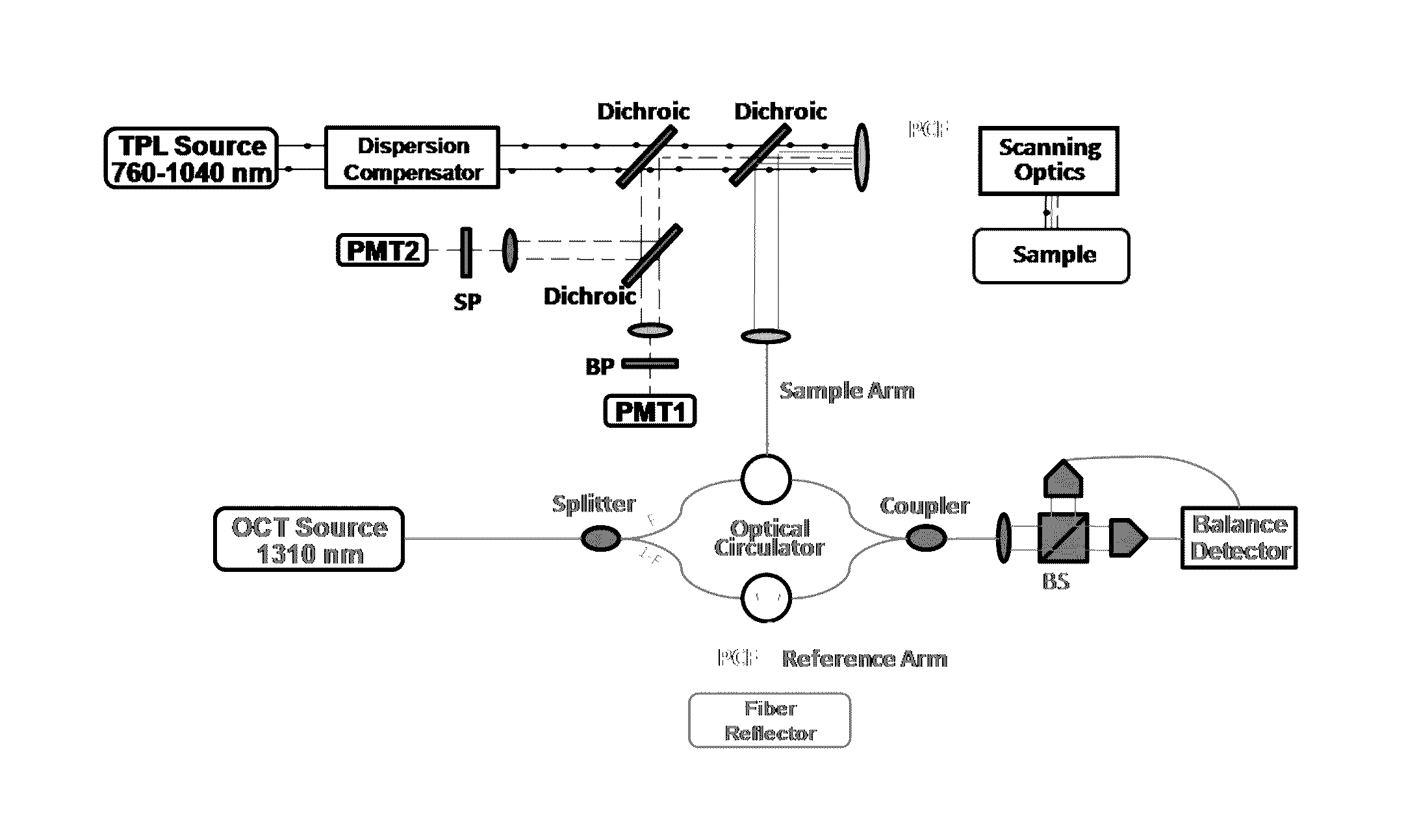
[0064]Examples of the catheter-based intensity OCT-TPL system (shown in FIGS. 5A and 5B) can incorporate a spectral-domain OCT system operating at 1310 nm combined with TPL using a tunable femtosecond laser excitation (e.g., 760-1040 nm, 6 nJ-5 μJ, 100 fs-1 ps, 500 kHz-80 MHz). A pulse compressor can be utilized to pre-compensate the group dispersion delay of femtosecond laser light to provide transform-limited pulses on the luminal surface. The imaging catheter is connected to a photonic crystal fiber (PCF) (e.g., LMA-20, NKT Photonics) of the OCT-TPL imaging system, which can enable single-mode propagation of both OCT light and TPL excitation light and transmission of TPL emission light (e.g. the OCT light and TPL excitation light are transmitted simultaneously). In certain embodiments, the PCF may comprise a 15 μm core (e.g., LMA-15).

[0065]FIG. 5A depicts a catheter-based intensity OCT-TPL imaging system comprising a beam splitter (BS); band...

example 2

Catheter-Based Polarization-Sensitive OCT-TPL System

[0071]One example of the catheter-based polarization-sensitive OCT-TPL system (shown in FIG. 6) can incorporate a spectral-domain polarization-sensitive OCT (PSOCT) system operating at 1310 nm combined with TPL using a tunable femtosecond laser excitation (e.g., 760-1040 nm, 6 nJ-5 μJ, 100 fs-1 ps, 500 kHz-80 MHz). The system in FIG. 6 comprises polarization maintaining fiber segments (PM1 and PM2) that act as an in-line fiber polarimeter; a polarization beam splitter (PBS); a band-pass filter (BP); a short-pass filter (SP); a photon multiplier tube (PMT); and a photonic crystal fiber (PCF).

[0072]The PSOCT system utilizes balanced detection and an in-line fiber polarimeter [29] to measure the polarization state of both reference light and interference fringes. An open optical switch in the sample path of the interferometer allows measurement of a signal containing only the polarization state of reference light (without interference...

example 3

Catheter-Based Spectral Domain Phase-Sensitive OCT-TPL System

[0073]One example of a catheter-based phase-sensitive OCT-TPL system (shown in FIG. 7) can incorporate a spectral-domain phase-sensitive OCT (PhSOCT) system operating at 1310 nm combined with TPL using a tunable femtosecond laser excitation (e.g., 760-1040 nm, 6 nJ-5 μJ, 100 fs-1 ps, 500 kHz-80 MHz). The system of FIG. 7 comprises a polarization beam splitter (BS); a band-pass filter (BP); a short-pass filter (SP); a photon multiplier tube (PMT); and a photonic crystal fiber (PCF).

[0074]A pulse compressor can be utilized to pre-compensate the group delay dispersion of femtosecond laser light to provide transform-limited pulses incident on the luminal surface of the vessel being imaged. The imaging catheter can be connected to a photonic crystal fiber (PCF) (e.g., LMA-20, NKT Photonics) of the OCT-TPL imaging system, which can enable single-mode propagation of both OCT light and TPL excitation light and transmission of TPL ...


PUM


Abstract

Exemplary embodiments of the present disclosure include a combined catheter-based optical coherence tomography-two-photon luminescence (OCT-TPL) imaging system. Exemplary embodiments further include methods to detect, and further characterize the distribution of cellular components (e.g., macrophage, collagen / elastin fiber, lipid droplet) in thin-cap fibroatheromas with high spatial resolution in vivo.

Description

CROSS-REFERENCE TO RELATED APPLICATIONS[0001]This application claims priority to U.S. Provisional Patent Application Ser. No. 61 / 785,030, filed Mar. 14, 2013, the contents of which are incorporated by reference herein.BACKGROUND INFORMATION[0002]Atherosclerosis and plaque rupture leading to myocardial infarction remain the leading cause of death worldwide [1]. Inflammation and underlying cellular and molecular mechanisms [2-4] contribute to atherogenesis from initiation through progression, plaque rupture and ultimately, thrombosis. The vulnerable plaque, recently defined by Virmani [5] as “thin-cap fibroatheroma”, results from inflammation and is characterized as having a thin fibrous cap typically less than 65 μm thick, increased infiltration of macrophages with decreased smooth muscle cells, and an increased lipid core size compared to stable plaques [6-8].[0003]Several cellular and molecular events that lead to rupture of thin-cap fibroatheromas are now understood and being util...

Claims


Application Information

Patent Timeline
Patent Type & Authority Patents(United States)
IPC IPC(8): G01B9/02A61B5/00
CPCG01B9/02091A61B5/0066G01B9/02007G01B9/02014G01B2290/70G02B21/0076G02B23/24G01B9/0203A61B1/24A61B5/0035A61B5/0071A61B5/0084A61B5/02007A61B5/6852A61B5/7425A61B2562/0233A61B2576/00A61K49/0013G02B21/16G02B23/2484
Inventor FELDMAN, MARCMILNER, THOMASWANG, TIANYIPHIPPS, JENNIFER
Owner RES DEVMENT FOUND
Why Eureka
Try Eureka