Oxygen mask

a mask and oxygen technology, applied in the field of oxygen masks, can solve the problems of reducing the oxygen supply, so as to achieve the effect of reducing the amount of oxygen supply

Active Publication Date: 2016-11-08
NIHON KOHDEN CORP
View PDF42 Cites 3 Cited by
  • Summary
  • Abstract
  • Description
  • Claims
  • Application Information

AI Technical Summary

Benefits of technology

[0013]It is therefore an object of the invention to provide an oxygen mask in which efficient oxygenation is realized by a small supply amount of oxygen, rebreathing is reduced, and the degree at which the expired gas is diluted by oxygen is reduced, thereby enabling the concentration of the expired gas to be correctly measured.

Problems solved by technology

However, the diffuser causes oxygen to directly flow into the nose and the mouth, and hence there is a problem in that the expired gas is diluted by oxygen and the concentration of the expired gas cannot be correctly measured.
Particularly, it is very difficult to perform the measurement on mouth respiration.
Therefore, also supplied oxygen is sucked, and there is a possibility that the expired gas is diluted.
In the oxygen supply which is performed through the tube, and which is disclosed in JP-A-2006-68471, there is a problem in that oxygenation is not performed in the case of mouth respiration.
Therefore, oxygen of a predetermined amount or more cannot be supplied.
In the oxygen supply which is performed through the mask, and which is disclosed in JP-A-2005-253925, there is a problem in that the interior of the mask is airtight and hence high concentration CO2 which has been expired is again inspired.
Therefore, there are problems such as that oxygen is wastefully used, and that, during attachment of the mask, the eyes are dried.

Method used


Image

  • Oxygen mask
  • Oxygen mask
  • Oxygen mask

Examples


Embodiment Construction

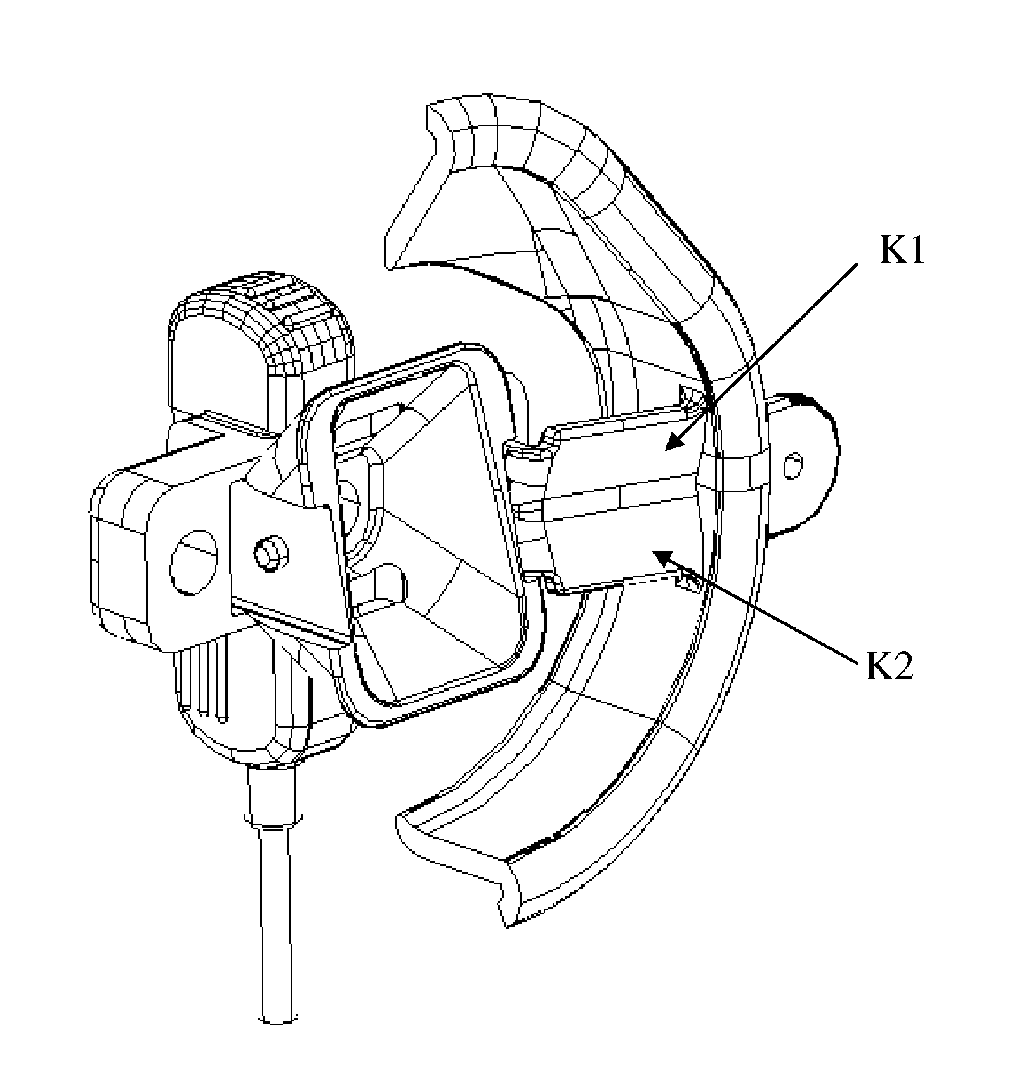
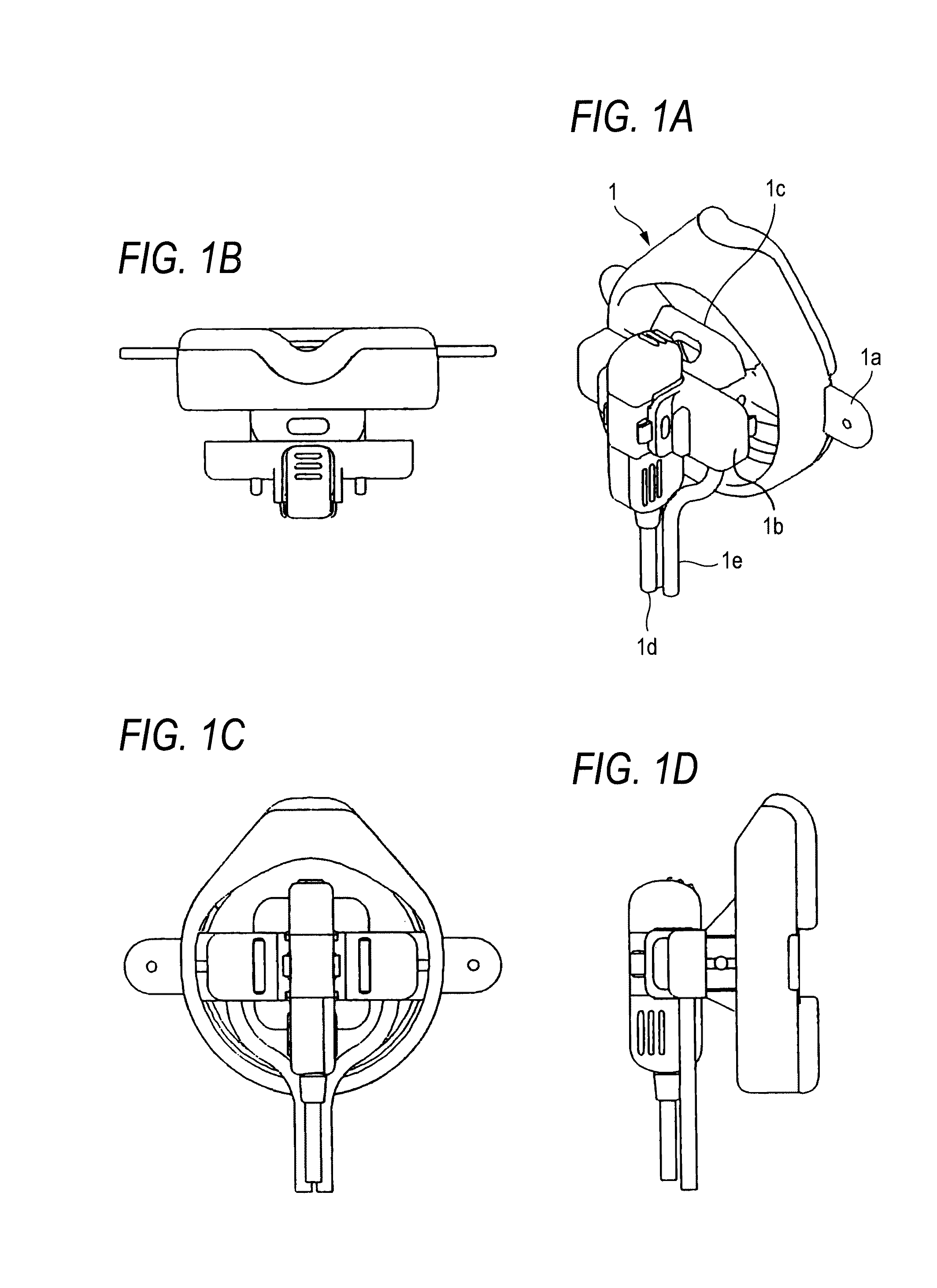
[0042]FIGS. 1A to 1D are views showing an example of the configuration of the oxygen mask of the invention in a state where an expired gas concentration measurement unit is attached to the mask.

[0043]FIG. 1A is a perspective view of an oxygen mask 1 in a state where an expired gas concentration measurement unit is attached to a mask, 1a denotes the mask, 1b denotes an oxygen blow out unit, 1c denotes an expired gas introduction unit, 1d denotes the expired gas concentration measurement unit, and 1e denotes an oxygen tube.

[0044]FIG. 1B is a top view of FIG. 1A, FIG. 1C is a front view, and FIG. 1D is a side view.

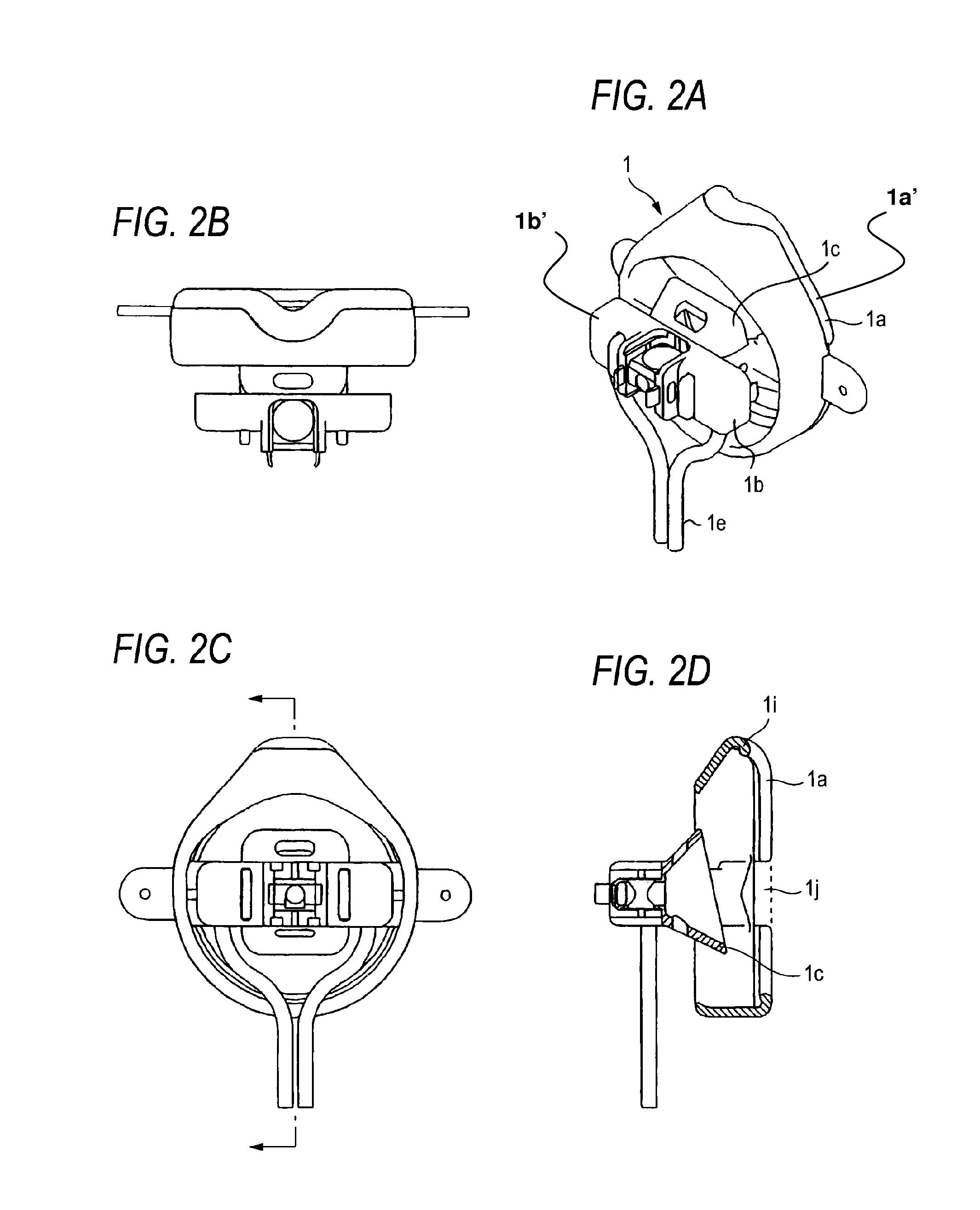
[0045]FIGS. 2A to 2D are views showing an example of the configuration of the oxygen mask 1 shown in FIGS. 1A to 1D in a state where the expired gas concentration measurement unit 1d is detached from the mask 1a.

[0046]FIG. 2A is a perspective view of the oxygen mask 1 in a state where the expired gas concentration measurement unit 1d is detached from the mask 1a.

[0047]FIG. ...


PUM


Abstract

An oxygen mask can include an oxygen supply unit and an attachment unit which is to be attached to a periphery of a nose or a nose and a mouth of a patient. The attachment unit includes an opening which communicates with external air and which is formed at a position to which, when the oxygen mask is attached to the patient, at least one of the nose and the mouth of the patient is opposed.

Description

BACKGROUND OF THE INVENTION[0001]The present invention relates to an oxygen mask which is attached to the patient to supply oxygen thereto, and more particularly to an oxygen mask to and from which an expired gas concentration measurement sensor is attachable and detachable.[0002]An oxygen diffuser which supplies oxygen to the patient is disclosed in JP-T-2004-507333. The oxygen diffuser disclosed in JP-T-2004-507333 is described as follows with reference to FIG. 8.[0003]The diffuser 20 shown in section in FIG. 8 has a body 31 formed from a wall 32, of somewhat triangular, cup-shaped appearance which follows the shape of the nose / mouth nexus of a patient. This wall extends from a base 33 where an oxygen outlet 34 is positioned, outwardly and upwardly to an edge 35 of triangular peripheral shape. As it approaches this edge 35, wall 32 becomes more “vertical” (with opposite sides being parallel) than outwardly extending. This shaping of the body wall permits a concentration of the oxy...

Claims


Application Information

Patent Timeline
Patent Type & Authority Patents(United States)
IPC IPC(8): A62B18/02A61M16/06A61M16/08
CPCA61M16/06A61M16/085A61M16/0816A61M2202/0208A61M2206/14A61M2230/432
Inventor TAKATORI, FUMIHIKOYAMAMORI, SHINJIINOUE, MASAYUKI
Owner NIHON KOHDEN CORP
Why Eureka
Try Eureka