Network virtualization system, physical node, and virtual interface identification method in virtual machine

a virtualization system and virtual machine technology, applied in the field of network virtualization system operation, can solve problems such as the complexity of network management and operation

Active Publication Date: 2016-11-08
NEC CORP
View PDF25 Cites 0 Cited by
  • Summary
  • Abstract
  • Description
  • Claims
  • Application Information

AI Technical Summary

Benefits of technology

[0043]According to the present invention, it is possible to provide a network virtualization system, a physical node, and a virtual interface identification method in a virtual machine capable of recognizing the correspondence relation between a virtual interface and a virtual NIC in the virtual machine without referring to the virtual network assignment result and without waiting for the start-up of the virtual machine.

Problems solved by technology

In recent years, as networks become larger, the management and operation of networks are getting more complicated.

Method used


Image

  • Network virtualization system, physical node, and virtual interface identification method in virtual machine
  • Network virtualization system, physical node, and virtual interface identification method in virtual machine
  • Network virtualization system, physical node, and virtual interface identification method in virtual machine

Examples


first exemplary embodiment

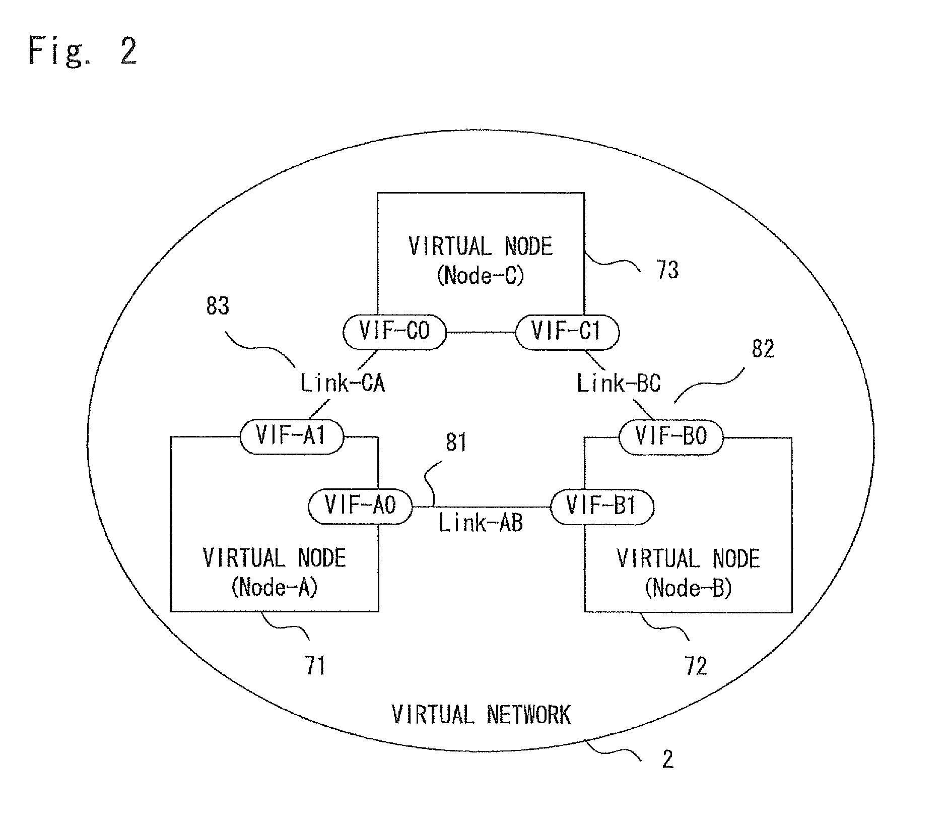
[0066]Exemplary embodiments of the present invention are explained hereinafter with reference to the drawings. In the following explanation, an overall configuration of a network system, a configuration of a physical node, and an operation of the physical node according to this exemplary embodiment are explained one by one. Note that in the following explanation, a node on a virtual network is simply referred to as “virtual node”, and a link on a virtual network is simply referred to as “virtual link”.

[0067]

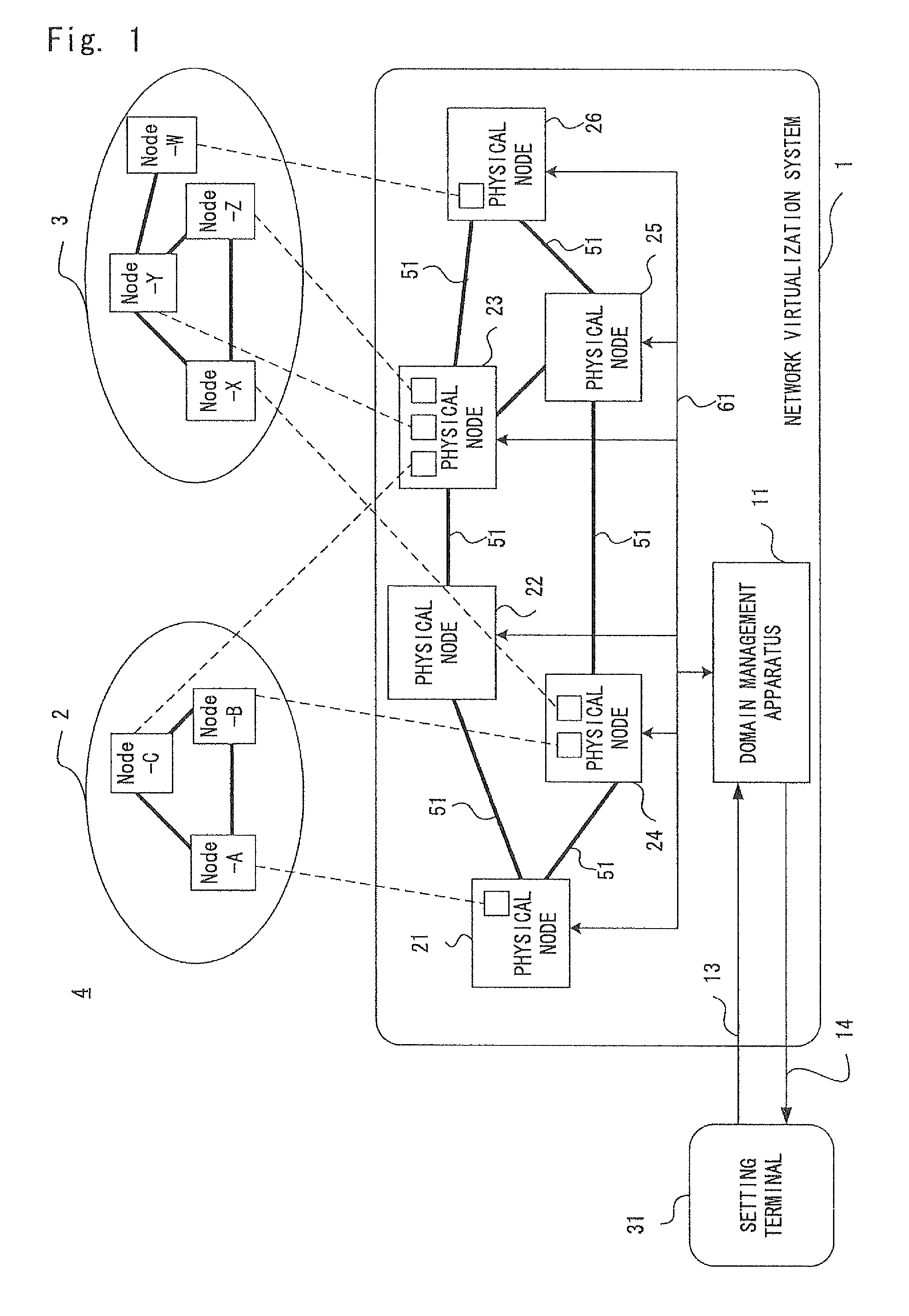
[0068]FIG. 1 is a block diagram showing an example of an overall configuration of a network system 4 including a network virtualization system 1 according to this exemplary embodiment of the present invention.

[0069]The network system 4 includes a setting terminal 31 and the network virtualization system 1.

[0070]The setting terminal 31 sends an instruction to create a virtualized network to the network virtualization system 1 under an instruction from another apparatus (not shown)...

first example

[0167]Next, a first example according to this exemplary embodiment of the present invention is explained with reference to FIGS. 13 and 14. Note that the configuration and the operation of a network virtualization system 1 according to the first example are equivalent to those of the first exemplary embodiment. Therefore, detailed explanation of the configuration and the operation that are equivalent to those of the first exemplary embodiment may be omitted as appropriate, and the following explanation is made with a particular emphasis on the configuration and operation that are unique to the first example.

[0168]Firstly, the assumptions for this example are summarized.

[0169]The definition shown in FIG. 16 is used as the virtual network definition of this example. The uppermost one (Node-A) of the three virtual node definitions shown in FIG. 16 is used as the virtual node definition of this example.

[0170]The physical node to be processed is the physical node 21 shown in FIG. 3. That...


PUM


Abstract

A domain management apparatus instructs physical nodes about the configuration of virtual nodes and virtual links of virtual networks. The physical nodes assign a virtual machine to a virtual node based on the definition of the virtual node contained in an instruction from the domain management apparatus. The physical nodes write a configuration associating virtual interfaces in the virtual node definition with virtual NICs on the virtual machine into a configuration file of the operating system to be started up on the virtual machine before the start-up of the virtual machine and, then, start up the virtual machine. Therefore, it is possible to recognize the correspondence relation between the virtual interface in the virtual node definition and the virtual NIC in the virtual machine without referring to the virtual network assignment result and without waiting for the start-up of the virtual machine.

Description

TECHNICAL FIELD[0001]The present invention relates to an operating method of a network virtualization system, and in particular to a virtual interface identification method in a virtual machine to be assigned to a virtual network node constituting a virtual network.BACKGROUND ART[0002]In recent years, as networks become larger, the management and operation of networks are getting more complicated. As a result, for example, the management of a network is conducted in such a manner that one of the apparatuses constituting the network undertakes a task of configuring another apparatus and configures that apparatus on behalf of the administrator (for example, see Patent literatures 1 and 2).[0003]Further, the management of a network is conducted in such a manner that instead of using the physical network constituting the network as it is, a virtual network(s) is constructed and used on the physical network for the purpose of the management or for securing the security.[0004]In a system ...

Claims


Application Information

Patent Timeline
Patent Type & Authority Patents(United States)
IPC IPC(8): G06F9/45G06F9/455H04L12/24G06F9/445
CPCG06F9/45533H04L41/0806H04L41/0895
Inventor MOTOKI, AKIHIRO
Owner NEC CORP
Why Eureka
Try Eureka