Magnetostrictive vibration power generation device

a power generation device and magnetic field technology, applied in the direction of magnetostrictive devices, piezoelectric/electrostrictive/magnetostrictive devices, piezoelectric/electrostriction/magnetostriction machines, etc., can solve problems such as damage risk, and achieve the effect of large power generation volume and efficient application of large vibration deformation

Active Publication Date: 2016-11-08
SUMITOMO RIKO CO LTD
View PDF6 Cites 4 Cited by
  • Summary
  • Abstract
  • Description
  • Claims
  • Application Information

AI Technical Summary

Benefits of technology

[0008]The present invention has been developed in view of the above-described matters as the background, and it is an object of the present invention to provide a magnetostrictive vibration power generation device with a novel structure which is able to avoid damage to the permanent magnet and realize an increase in durability, while effectively realizing vibration power generation using the magnetostrictive element.

Problems solved by technology

However, a typical permanent magnet formed with ferrite sintered body or the like is inferior to the load bearing capacity, so when the permanent magnet is arranged on the magnetic path for which the vibrational load is input, there is a risk of damage.

Method used


Image

  • Magnetostrictive vibration power generation device
  • Magnetostrictive vibration power generation device
  • Magnetostrictive vibration power generation device

Examples


first embodiment

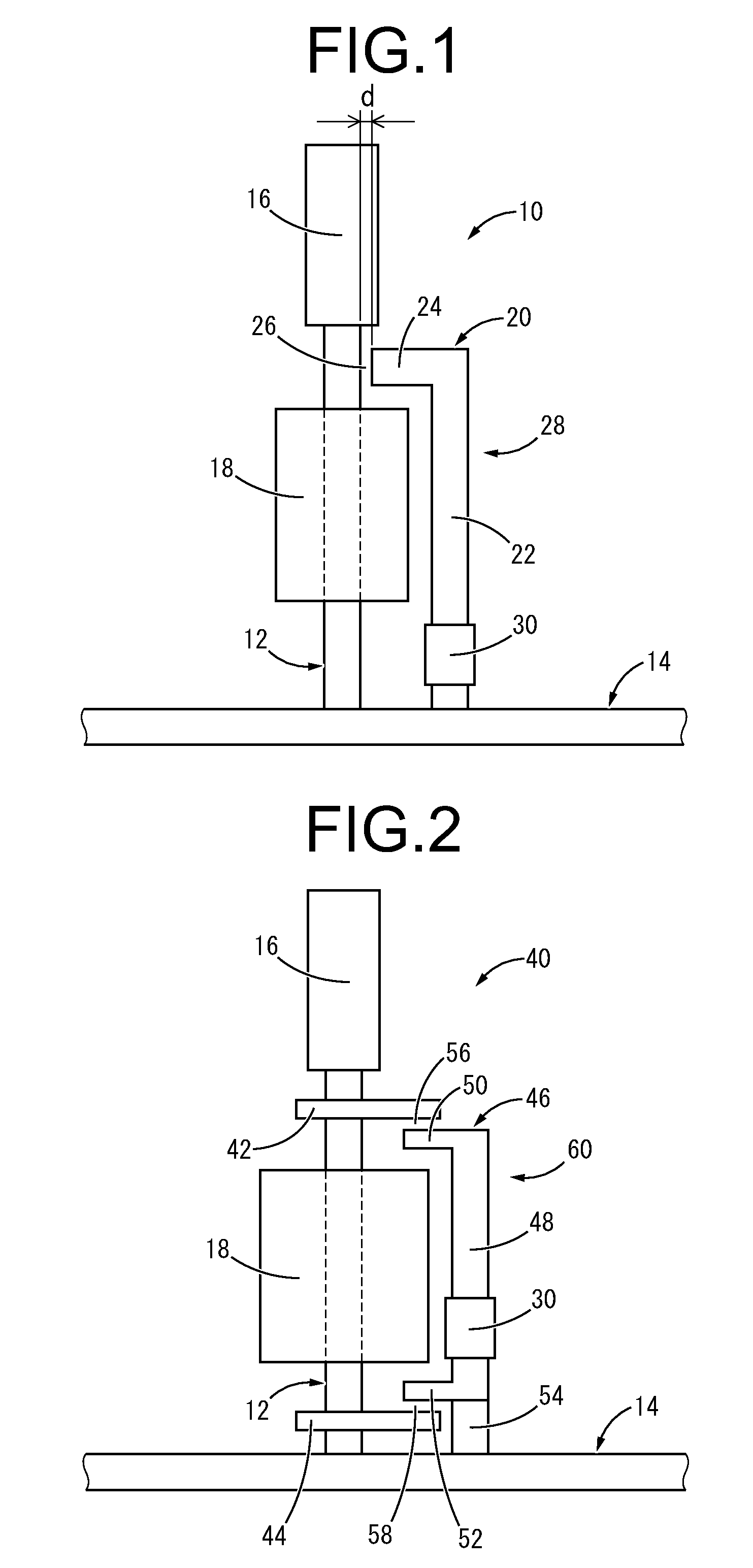
[0049]FIG. 1 shows a magnetostrictive vibration power generation device 10 (hereafter called “vibration power generation device 10”) as the present invention. The vibration power generation device 10 is equipped with a magnetostrictive element 12 as a power generating element that converts vibration energy to electric energy. With the description hereafter, the vertical direction means the vertical direction in FIG. 1 as a rule.

[0050]In more detail, the magnetostrictive element 12 is formed of a magnetostrictive material and has a longitudinal shape extending in a straight line in the vertical direction, and with this embodiment, has a solid rod shape extending at the small diameter circular cross section. The forming material of the magnetostrictive element 12 is not particularly restricted as long as it is an item for which sufficient change of magnetic permeability can occur in relation to deformation, but an iron type magnetostrictive material which has excellent strength is pre...

third embodiment

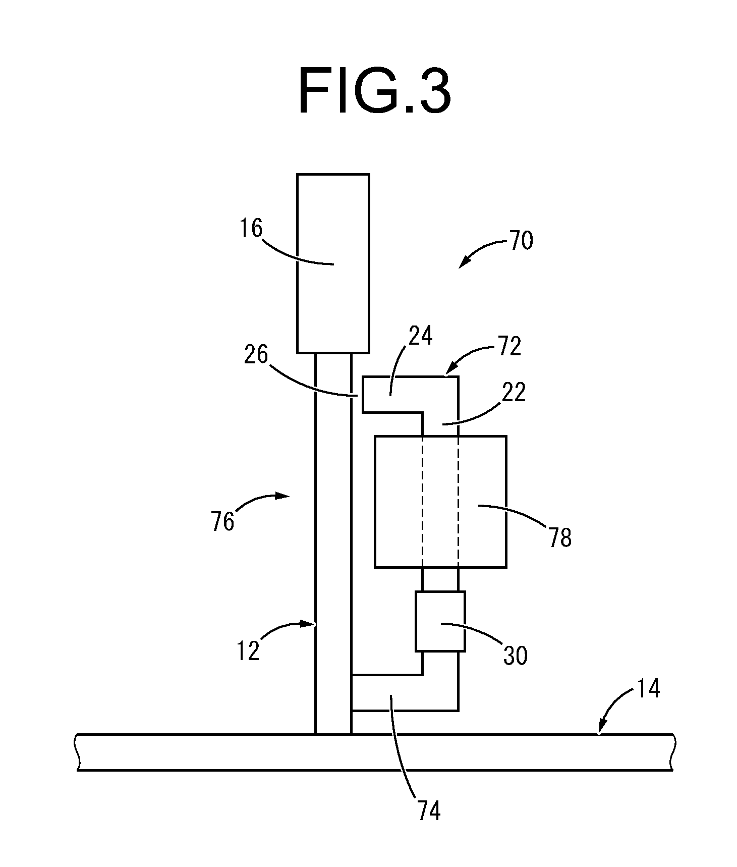
[0069]FIG. 3 shows a magnetostrictive vibration power generation device 70 as the present invention. The vibration power generation device 70 is constituted including a yoke member 72. The yoke member 72 is equipped with a rod shaped main unit part 22 arranged with a gap at the side of the magnetostrictive element 12 and extending roughly parallel, a projecting part 24 projecting toward the magnetostrictive element 12 from the top end of the main unit part 22, and a coupling support part 74 that couples the bottom end of the main unit part 22 to the magnetostrictive element 12. Also, a closed magnetic path 76 is formed by the magnetostrictive element 12 and the yoke member 72.

[0070]Furthermore, the permanent magnet 30 is fixed to the main unit part 22 of the yoke member 72 constituting the closed magnetic path 76, and a coil 78 is wound, the magnetic flux of the permanent magnet 30 is applied as a bias magnetic field to the closed magnetic path 76, and the bias magnetic field pierce...

fourth embodiment

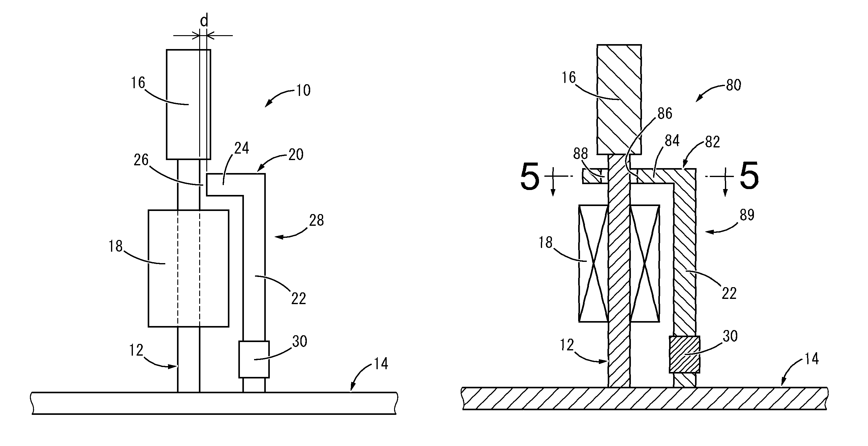
[0073]FIG. 4 and FIG. 5 show a magnetostrictive vibration power generation device 80 as the present invention. With the vibration power generation device 80, a yoke member 82 is equipped with a main unit part 22 extending in parallel with the magnetostrictive element 12, and a projecting part 84 projecting toward the magnetostrictive element 12 from the top end of the main unit part 22.

[0074]As shown in FIG. 4 and FIG. 5, the projecting part 84 has a roughly rectangular plate shape that expands in the axis-perpendicular direction, and extends out past the magnetostrictive element 12, and also, has an insertion hole 86 formed piercing through vertically, and has the magnetostrictive element 12 inserted through the insertion hole 86. This insertion hole 86 has a circular cross section with a diameter larger than the diameter of the magnetostrictive element 12, and in a state with the magnetostrictive element 12 inserted through the insertion hole 86, a ring shaped gap 88 that is conti...


PUM


Abstract

A magnetostrictive vibration power generation device including: a longitudinal magnetostrictive element formed of a magnetostrictive material and configured to be attached to a vibrating member at at least one end part thereof; a coil wound on a closed magnetic path constituted including the magnetostrictive element; and a permanent magnet arranged so as to apply a bias magnetic field to the closed magnetic path. A yoke member formed of a magnetic material is arranged in parallel at a side of the magnetostrictive element, and the closed magnetic path is formed including the magnetostrictive element and the yoke member, the permanent magnet is attached to the yoke member on the closed magnetic path, and the yoke member is allowed relative displacement in relation to the magnetostrictive element on at least one side in a magnetic path lengthwise direction of the closed magnetic path.

Description

INCORPORATED BY REFERENCE[0001]The disclosure of Japanese Patent Application No. 2013-016064 filed on Jan. 30, 2013, including the specification, drawings and abstract is incorporated herein by reference in its entirety. This is a Continuation of International Application No. PCT / JP2013 / 084710 filed on Dec. 25, 2013.BACKGROUND OF THE INVENTION[0002]1. Field of the Invention[0003]The present invention relates to a vibration power generation device that generates power by converting vibration energy to electric energy, and particularly to a magnetostrictive vibration power generation device that uses a magnetostrictive effect by deformation of a magnetostrictive element.[0004]2. Description of the Related Art[0005]From the past, vibration power generation devices that convert vibration energy to electric energy and use it have been proposed, and research and development has been progressing to handle the increase in demand for energy saving in recent times. These vibration power gener...

Claims


Application Information

Patent Timeline
Patent Type & Authority Patents(United States)
IPC IPC(8): H02N2/18H01L41/12
CPCH02N2/188H01L41/125H10N35/101
Inventor HASEGAWA, KOICHIKURIKUMA, HAJIME
Owner SUMITOMO RIKO CO LTD
Why Eureka
Try Eureka