Auxiliary steam generator system for a power plant

a technology power plant, which is applied in the direction of machines/engines, mechanical equipment, light and heating equipment, etc., can solve the problems of large space requirements of auxiliary steam generators, insufficient steam generated by actual steam generation processes, and inability to provide additional steam, so as to achieve the effect of drastically reducing installation costs

Inactive Publication Date: 2016-11-15
SIEMENS AG
View PDF29 Cites 0 Cited by
  • Summary
  • Abstract
  • Description
  • Claims
  • Application Information

AI Technical Summary

Benefits of technology

[0005]An aspect relates to an auxiliary steam generator system as a result of which the disadvantages from the prior art are avoided, and, above all, the installation costs can be drastically reduced. Moreover, it is the object of the invention to disclose a method for auxiliary steam generation, as a result of which the disadvantages from the prior art are avoided.

Problems solved by technology

For additional processes, especially starting modes or operating states, conventional power plants with a water-steam cycle require additional steam which possibly cannot be provided by means of the actual steam generation process.
The steam that can be generated by means of the actual steam generation process in this case may possibly not be sufficient, or not totally sufficient, for maintaining the pressure in the feed-water tank or for the operation of other auxiliary systems of the power plant.
Such auxiliary steam generators represent a high investment in the construction of power plants, especially as a result of the costly and complex connecting of the auxiliary steam generator into the water-steam cycle and to the auxiliary steam systems.
As a result of the complex connections, the auxiliary steam generators have a large space requirement.
Moreover, they require additional expenditure approval during construction.
Since the auxiliary steam generators are provided especially for specific operations, they are not required during normal operation of the power plant, but, however, give rise to running costs or efficiency losses since they have to be kept hot electrically, or via steam from the water-steam cycle of the power plant.
They also give rise to regular and not insignificant maintenance costs.
A conventional auxiliary boiler has to be kept hot electrically or via steam and also has high outage losses.

Method used


Image

  • Auxiliary steam generator system for a power plant
  • Auxiliary steam generator system for a power plant
  • Auxiliary steam generator system for a power plant

Examples


Embodiment Construction

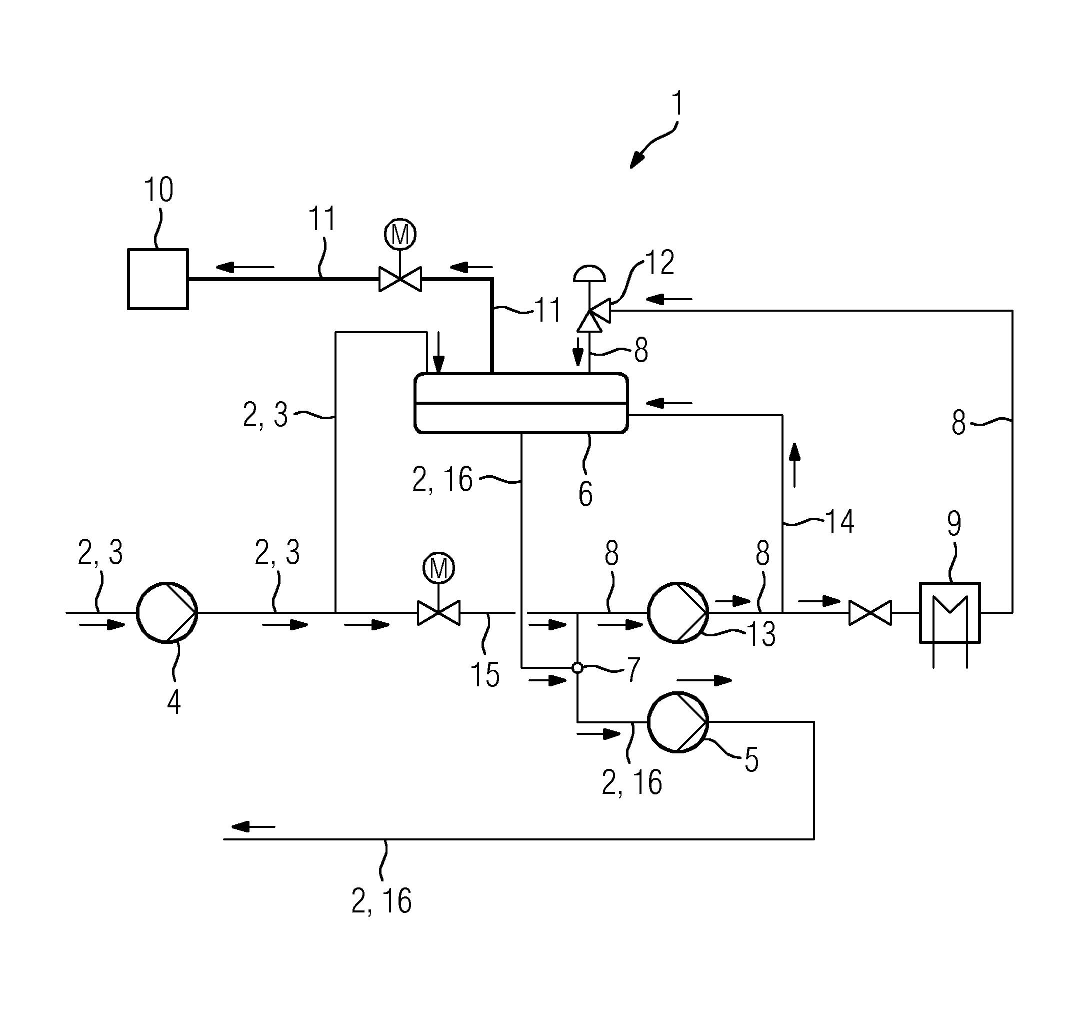
[0029]Shown in FIG. 1 is an auxiliary steam generator system 1, as can be integrated into a fossil-fired power plant or a solar power plant. The power plant comprises a water-steam cycle 2, of which only the section of the condensate line 3 is shown here.

[0030]In essence, a condensate pump 4 and a pressure accumulating vessel 6 are connected into the condensate line 3, and a feed-water pump 5 is connected into the feed-water line 16. By means of the condensate pump 4, condensate is delivered to the pressure accumulating vessel 6. In the pressure accumulating vessel, the condensate is degassed, mixed and stored before it is pumped again by means of the feed-water pump 5 through the feed-water line 16 into the water-steam cycle 2.

[0031]In accordance with described embodiments, provision is now made for a feed-water extraction line 8 which is connected at a branch point 7 to the feed-water line 16 between the pressure accumulating vessel 6 and the feed-water pump 5. Not shown here is a...


PUM


Abstract

An auxiliary steam generator system for a power plant, comprising a water-steam circuit, which has a condensate line and a feed-water line, wherein a condensate pump is connected in the condensate line and a feed-water pump is connected in the feed-water line, and wherein a pressure accumulating vessel is connected between the condensate pump and the feed-water pump, and wherein a feed-water take-off line is connected to the water-steam circuit at a branch-off point after the pressure accumulating vessel is provided. The feed-water take-off line is connected to the pressure accumulating vessel and a heating device is connected in the feed-water take-off line.

Description

CROSS-REFERENCE TO RELATED APPLICATIONS[0001]This application claims priority to PCT Application No. PCT / EP2012 / 074333, having a filing date of Dec. 4, 2012, based off of DE 102012200741.5 having a filing date of Jan. 19, 2012, the entire contents of which are hereby incorporated by reference.FIELD OF TECHNOLOGY[0002]For additional processes, especially starting modes or operating states, conventional power plants with a water-steam cycle require additional steam which possibly cannot be provided by means of the actual steam generation process. Counted among these specific operating states are especially transient operating states, operational outages, partial load operation or starting up and shutting down processes. Auxiliary steam is therefore required for example during an operational outage for maintaining pressure or for maintaining heat in the feed-water tank and also for gland steam supply to the steam turbine. The steam that can be generated by means of the actual steam gen...

Claims


Application Information

Patent Timeline
Patent Type & Authority Patents(United States)
IPC IPC(8): F01K23/06F22D11/02F01K3/16F22D3/00F01K13/00F01K7/16F03G6/00F01K9/00
CPCF01K13/006F01K3/16F01K7/16F01K9/00F03G6/003F22D3/00F22D11/02Y02E10/46
Inventor EDELMANN, HEINERREISSIG, MARKSATTELBERGER, MARCSCHRIEF, ANDRE
Owner SIEMENS AG
Why Eureka
Try Eureka