Photometer and method for compensating for ambient temperature changes in a photometer

a photometer and ambient temperature technology, applied in the field of photometers, can solve the problems of loss of sensitivity, thermistor can only be used to compensate, and the accuracy is not high enough for such applications

Active Publication Date: 2016-11-22
SPECTRO SCI INC
View PDF22 Cites 2 Cited by
  • Summary
  • Abstract
  • Description
  • Claims
  • Application Information

AI Technical Summary

Benefits of technology

[0006]When a thermistor is attached to the detector TO can, the resulting accuracy is not high enough for such applications. For example, the temperature at the location of the thermistor could be different than the temperature at another location on the TO can or different than the temperature of an individual pyroelectric detector element. Different pyroelectric detector elements, for example, may be at different temperatures. Moreover, a thermistor can typically only be used to compensate for large environmental temperature changes on the order of 1-25 Kelvin. Further if the design of the photometer only is such that the source and detector are mounted co-linearly with no further attempt to direct the incident radiation through the sample and into the detector, it is often the case that a significant amount of radiation passing through the sample will not reach the detector (e.g., 20-80%) resulting in a loss of sensitivity. By using a waveguide, transmission efficiency can be significantly enhanced. Furthermore the waveguide can ensure that the radiation profile is matched to the detector.
[0007]In this invention, the temperature of an individual pyroelectric detector may be measured electronically to account for even small changes in ambient temperatures as opposed to changes in temperature caused by incident radiation, thus resulting in a highly stable and sensitive photometer system.
[0009]Also, a waveguide which maximizes signal throughput acts in concert to produce maximum signal-to-noise ratio capabilities to enable the analysis of trace impurities in a fairly simple photometer system.

Problems solved by technology

When a thermistor is attached to the detector TO can, the resulting accuracy is not high enough for such applications.
Moreover, a thermistor can typically only be used to compensate for large environmental temperature changes on the order of 1-25 Kelvin.
Further if the design of the photometer only is such that the source and detector are mounted co-linearly with no further attempt to direct the incident radiation through the sample and into the detector, it is often the case that a significant amount of radiation passing through the sample will not reach the detector (e.g., 20-80%) resulting in a loss of sensitivity.

Method used


Image

  • Photometer and method for compensating for ambient temperature changes in a photometer
  • Photometer and method for compensating for ambient temperature changes in a photometer
  • Photometer and method for compensating for ambient temperature changes in a photometer

Examples


Embodiment Construction

[0032]Aside from the preferred embodiment or embodiments disclosed below, this invention is capable of other embodiments and of being practiced or being carried out in various ways. Thus, it is to be understood that the invention is not limited in its application to the details of construction and the arrangements of components set forth in the following description or illustrated in the drawings. If only one embodiment is described herein, the claims hereof are not to be limited to that embodiment. Moreover, the claims hereof are not to be read restrictively unless there is clear and convincing evidence manifesting a certain exclusion, restriction, or disclaimer.

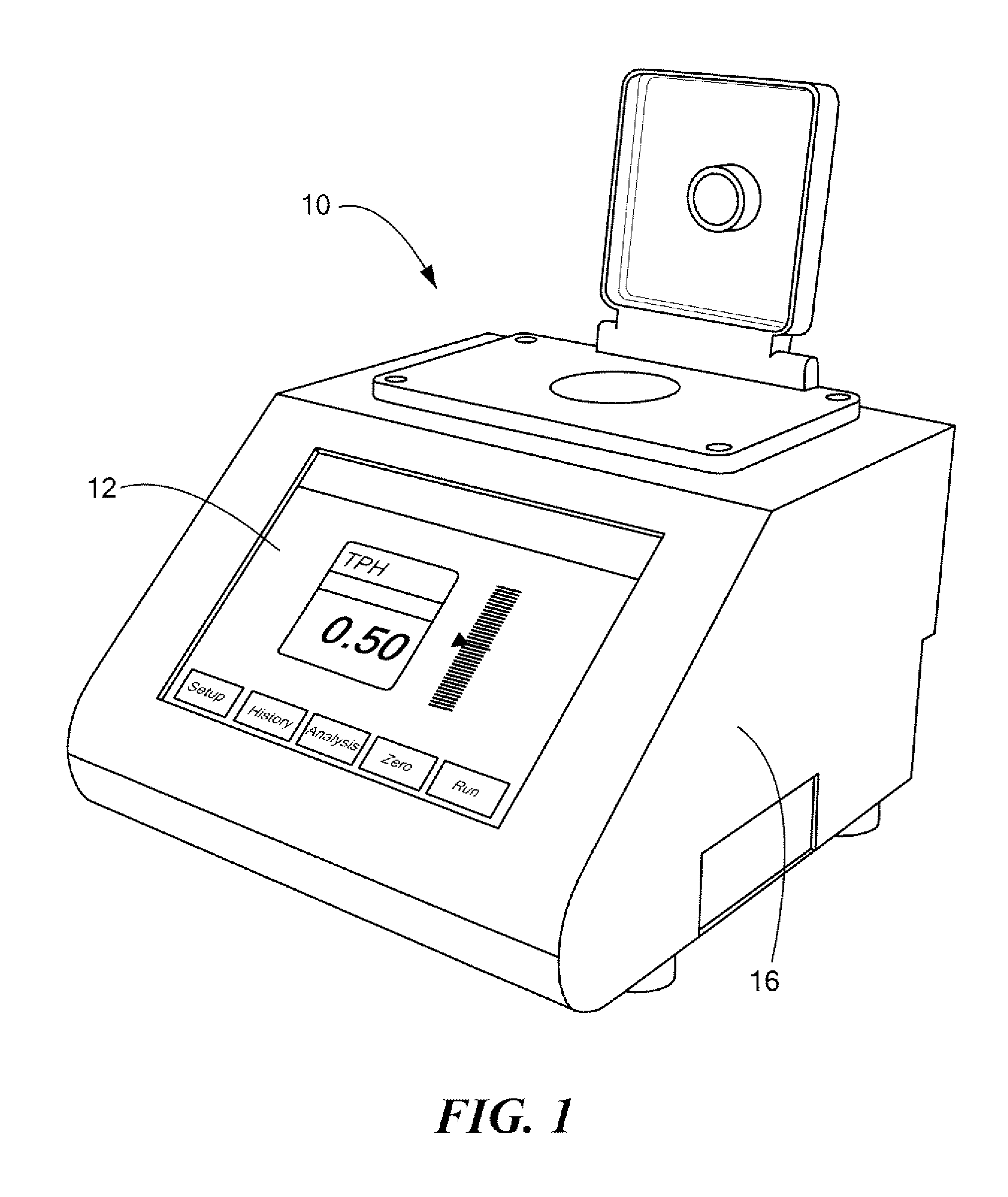
[0033]FIG. 1 shows an example of a photometer 10 with input / output section 12 (e.g., including a touch screen). Photometer 10 can be used to test a sample and to very accurately report, for example, the amount of oil in a water sample. Preferred is a system which can detect very small (e.g., parts per million) oil in a wate...


PUM

PropertyMeasurementUnit
diameteraaaaaaaaaa
diameteraaaaaaaaaa
diameteraaaaaaaaaa

Abstract

A photometer and associated method includes a source of radiation to be directed through a sample and a detector stage configured to measure radiation after passing through the sample. A voltage follower circuit is connected to the detector and is configured to provide an output signal which varies as a function of the detector output voltage and which varies as a function of the ambient temperature. A processing subsystem is configured to determine a temperature compensation factor from the voltage follower circuit output signal.

Description

FIELD OF THE INVENTION[0001]The subject invention relates to photometers.BACKGROUND OF THE INVENTION[0002]In a photometer used to measure, for example, soot levels in lubrication oils, the amount of oil in waste water, and the like, a source directs infrared radiation through a sample and to one or more detectors. See, for example, U.S. Pat. Nos. 2,648,249; 3,937,962; 3,818,198; 5,041,723; 5,734,165; and 6,420,708 incorporated herein by this reference and P. A. Wilks “In-line Infrared Sensors Covering the Mid Infrared from 2 to 14 μm (5000 to 700 cm−1)”, Vibrational Spectroscopy-Based Sensor Systems, Steven D. Christesen, Arthur J. Sedlacek III, Editors, Proceeding of SPIE Vol. 4577 (2002), also incorporated herein by this reference.[0003]Pyroelectric detector elements may be placed on top of the base of a TO can package and each detector element is associated with a different filter. See also U.S. Pat. No. 4,943,800 incorporated herein by the reference. In operation, a pyroelectric...

Claims


Application Information

Patent Timeline
Patent Type & Authority Patents(United States)
IPC IPC(8): H01J40/14G01N21/59
CPCG01N21/59G01N2201/1211G01N21/3577G01N21/552G01N33/1833
Inventor CHAMBERLIN, DAVID B.GLOWINSKI, MICHAEL EDWARDLAVERY, DONALD STANTON
Owner SPECTRO SCI INC
Why Eureka
Try Eureka