Electromagnetic radiation detector with micro-encapsulation, and device for detecting electromagnetic radiation using such detectors

a technology of electromagnetic radiation and detector, applied in the field of electromagnetic radiation detection, can solve the problems of large equipment items, large and inconvenient use, and achieve the effect of substantially eliminating the footprint of anchoring points and reducing sensitivity losses

Active Publication Date: 2014-10-21
ULIS SAS
View PDF15 Cites 2 Cited by
  • Summary
  • Abstract
  • Description
  • Claims
  • Application Information

AI Technical Summary

Benefits of technology

[0047]According to one aspect of the invention, the anchoring points and electrical connections of the ends of the arms that support the membranes are formed at the interfaces between these two parts. Because of this, the sensitivity losses inherent in detectors according to the prior art due to the limits placed on the length of the arms and the footprint of the anchoring points are substantially eliminated.
[0048]According to one advantageous aspect of the invention, peripheral facets are provided at the level of the upper walls or windows in the vicinity of the side walls so as to compensate for most of the residual reduction in the fill factor due to the footprint of said walls. More precisely, these peripheral facets which slope towards the substrate or have a rounded profile are capable of deflecting most of the incident electromagnetic radiation in the vicinity of the boundaries between two micro-sites towards one or other of the adjacent micro-cavities, essentially without any intermediate loss in terms of the signals that are available for forming an image.

Problems solved by technology

The main attraction of this type of technology is the fact that a large number of hermetically sealed components can be obtained simultaneously by using a relatively limited number of parts and operations, hence saving costs.
The overall process of producing the depressurised enclosure, including final cutting which cannot be performed on both substrates simultaneously because the electrical input / output connections formed outside the enclosure on the substrate of the readout circuit have to be exposed, nevertheless remains relatively complex.
All these techniques can be mastered but they require numerous items of expensive equipment.
In addition, the technologies involved in brazing large-area substrates so that all the final components are collectively hermetically sealed have to be mastered, and this imposes particular constraints in terms of the flatness and geometrical quality of the two surfaces that are to be joined.
Finally, these operations are carried out when the extremely fragile sensitive elements are exposed on the surface of the readout circuit substrate and this makes the operation especially tricky with regard to the integrity of the structures and the risk of particulate contamination.
Although they undoubtedly represent progress in terms of industrial manufacturing, these techniques nevertheless remain relatively complex and costly.
This results in a loss of sensitivity associated with limitations on the practicable length of said arms; this length defines the thermal resistance between the membrane and the substrate.
In other words, these geometrical considerations impose substantial limits on the fill factor, especially in case of narrower pitches.

Method used


Image

  • Electromagnetic radiation detector with micro-encapsulation, and device for detecting electromagnetic radiation using such detectors
  • Electromagnetic radiation detector with micro-encapsulation, and device for detecting electromagnetic radiation using such detectors
  • Electromagnetic radiation detector with micro-encapsulation, and device for detecting electromagnetic radiation using such detectors

Examples


Embodiment Construction

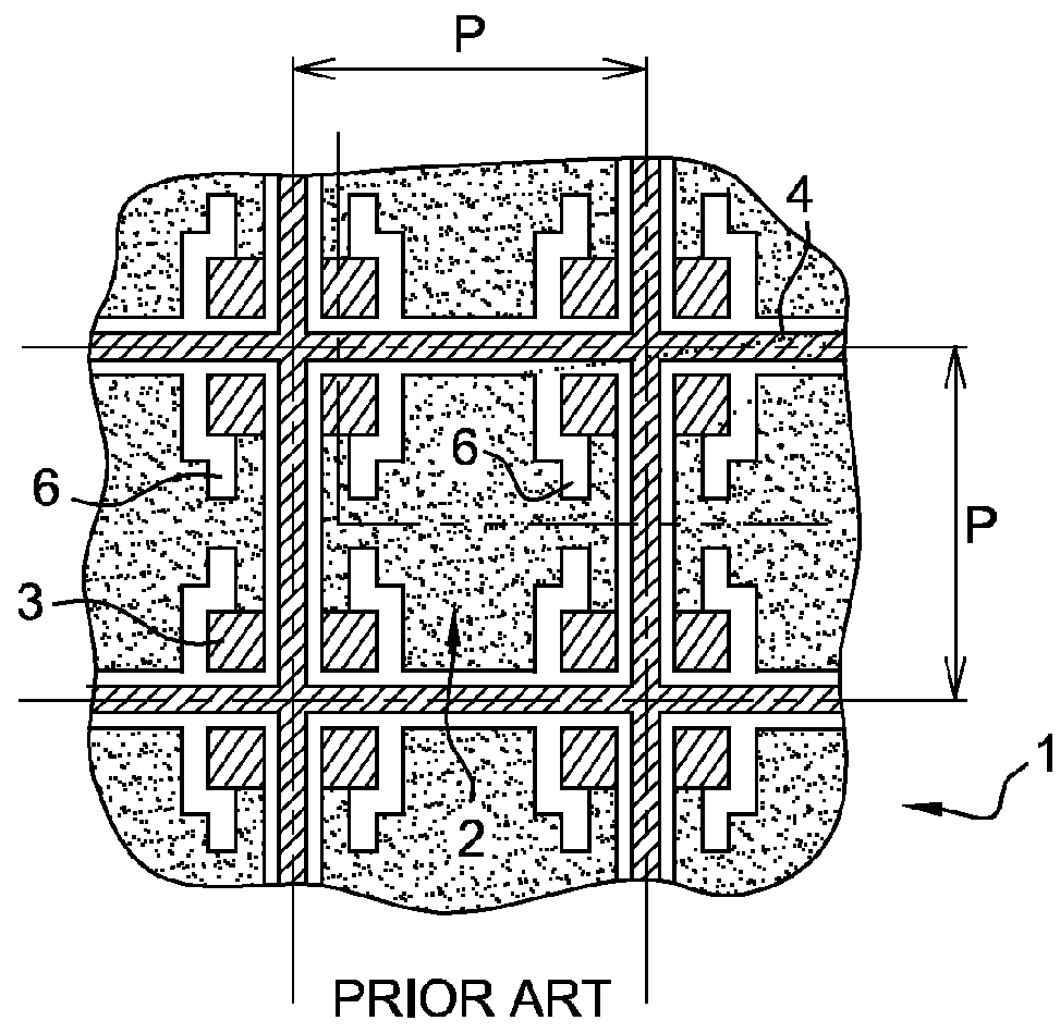
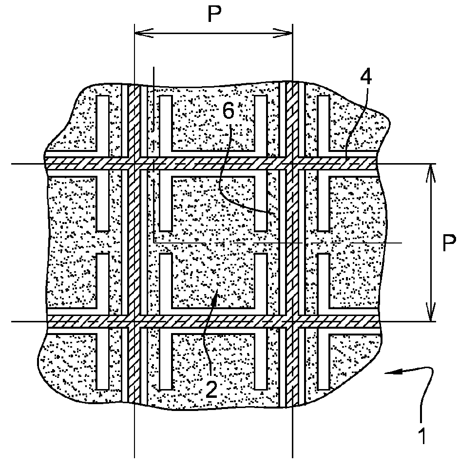
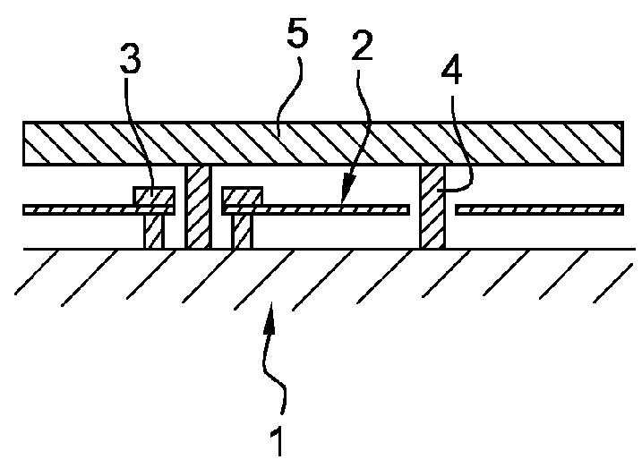
[0082]FIG. 2A schematically shows a design according to the invention in a form devoid of functional elements that are used for electrically wiring, exhausting and hermetically sealing the micro-sites. These elements are as follows:[0083]initial substrate 1 on which all the structures are collectively formed;[0084]sensitive membranes 2 of the detectors in an array with a repetition pitch p, supported by their support arms 6 which extend as far as peripheral walls 4 into which they are inserted;[0085]walls or side walls 4 formed by superposed parts 4A and 4B;[0086]upper covers or windows 5.

[0087]FIG. 2B supplements the description with regard to the insertion of support arms 6 of membranes 2. The anchoring structures, in their traditional form shown schematically in FIGS. 1A and 1B, have now been eliminated and arms 6 extend as far as the joint between the two parts 4A and 4B of walls 4 which act as anchoring structures formed on the axis of symmetry between sensitive sites, as is cu...


PUM


Abstract

This electromagnetic radiation detector consists of a plurality of elementary detection micro-sites, each including a micro-detector provided with a membrane (2) that is sensitive to the radiation in question and each being provided in a micro-cavity or micro-capsule defined by a substrate (1), by an upper wall (5) used as a window that is transparent to said radiation and by side walls (4), said membrane (2) being suspended above substrate (1) by means of at least two support arms (6) that include an electrically conducting layer (17), with the ends of said arms (6) being anchored in side walls (4).

Description

TECHNICAL FIELD OF THE INVENTION[0001]The present invention relates to the field of detecting electromagnetic radiation, more precisely imaging and thermal pyrometry. More particularly, the present invention relates to a device for detecting infrared radiation comprising an array of elementary thermal detectors.BACKGROUND OF THE INVENTION[0002]In the field of detectors used for infrared imaging or thermography (pyrometry), it is known to use devices configured in the form of an array and capable of operating at ambient temperature which use a variation in a physical unit of a material or an assembly of appropriate materials as a function of temperature at around 300 K, i.e. without cooling. In the particular case of bolometric detectors which are the most widely used, this physical unit is electrical resistivity. Other electrical units such as dielectric constant, polarisation and even non-electrical units such as differential thermal expansion, refractive index, etc. can be exploit...

Claims


Application Information

Patent Timeline
Patent Type & Authority Patents(United States)
IPC IPC(8): G01J5/20G01J5/00G01J5/08H01L31/09G01J5/02
CPCG01J5/0875G01J5/023G01J5/02H01L31/09G01J5/20G01J5/08G01J5/0235
Inventor VILAIN, MICHEL
Owner ULIS SAS
Why Eureka
Try Eureka