Wireless power transmission device and power transfer system

Active Publication Date: 2019-11-21
TOYOTA JIDOSHA KK
View PDF0 Cites 2 Cited by
  • Summary
  • Abstract
  • Description
  • Claims
  • Application Information

AI Technical Summary

Benefits of technology

[0020]The oscillation signal may be a rectangular wave signal of which amplitude indicating magnitude of the first frequency manipulation amount increases and decreases stepwise. The number of steps of the rectangular wave signal may increase by one each time increasing manipulation is performed by the first generator and the number of steps of the rectangular wave signal may decrease by one each time decreasing manipulation is performed by the first generator. By increasing and decreasing an amplitude stepwise, occurrence of pulsation of output power at the time of increase and decrease in amplitude can be suppressed.
[0021]In the wireless power transmission device, t

Problems solved by technology

In such a method, however, when sensitivity of variation in current to frequency manipulation becomes lower, extreme value search will poorly proceed and the drive frequency for the inverter (and hence a frequency of output power from the inverter) cannot be controlled to an extrem

Method used


Image

  • Wireless power transmission device and power transfer system
  • Wireless power transmission device and power transfer system
  • Wireless power transmission device and power transfer system

Examples


Example

[0032]An embodiment of the present disclosure will be described in detail below with reference to the drawings. The same or corresponding elements in the drawings have the same reference characters allotted and description thereof will not be repeated.

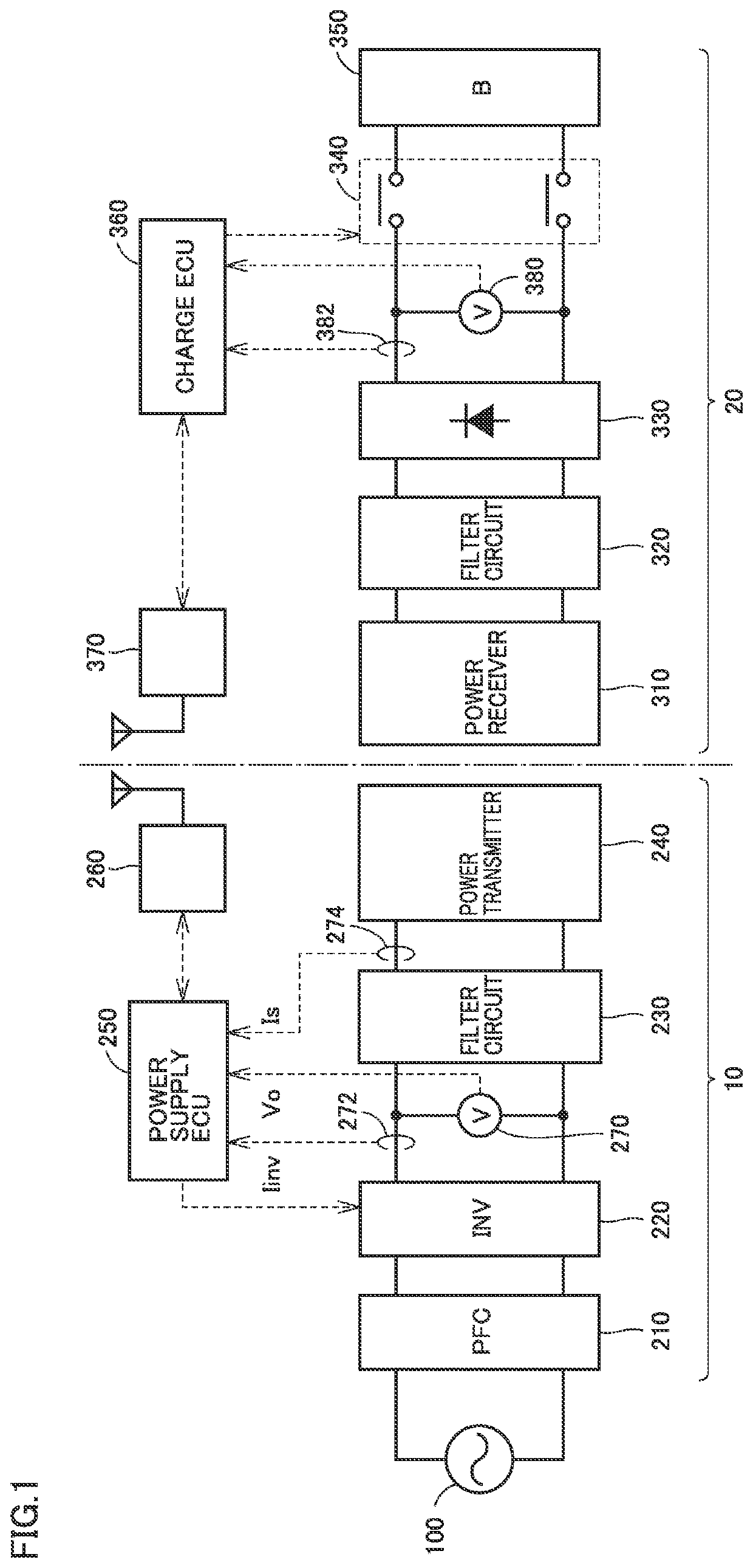
[0033]FIG. 1 is a diagram of an overall configuration of a power transfer system according to an embodiment of the present disclosure. Referring to FIG. 1, the power transfer system includes a power transmission device 10 and a power reception device 20. Power reception device 20 is mounted, for example, on a vehicle which can travel with electric power supplied from power transmission device 10 and stored therein. Though a resonance scheme is adopted as a wireless power transfer scheme in this embodiment, another scheme (electromagnetic induction scheme and the like) may be adopted.

[0034]Power transmission device 10 includes a power factor correction (PFC) circuit 210, an inverter 220, a filter circuit 230, and a power transmitter 240...


PUM


Abstract

A power supply ECU is configured to carry out extreme value search control for searching for a frequency at which a detected value of power loss is minimized, by oscillating a frequency of output power from an inverter. Then, the power supply ECU determines whether or not extreme value search in extreme value search control is poorly proceeding, and when extreme value search is poorly proceeding, the power supply ECU increases an amplitude of frequency oscillation of output power from the inverter.

Description

[0001]This nonprovisional application is based on Japanese Patent Application No. 2018-095962 filed with the Japan Patent Office on May 18, 2018, the entire contents of which are hereby incorporated by reference.BACKGROUNDField[0002]The present disclosure relates to a wireless power transmission device and a power transfer system and particularly to a technique for controlling an inverter in a wireless power transmission device configured to wirelessly transmit power to a power reception device.Description of the Background Art[0003]A power transfer system configured to wirelessly transfer power from a power transmission device to a power reception device has been known (see, for example, Japanese Patent Laying Open No. 2013-154815, Japanese Patent Laying Open No. 2013-146154, Japanese Patent Laying Open No. 2013-146148, Japanese Patent Laying Open No. 2013-110822, Japanese Patent Laying Open No. 2013-126327, and Japanese Patent Laying Open No. 2017-5865). Japanese Patent Laying Ope...

Claims


Application Information

Patent Timeline
IPC IPC(8): H02J50/12
CPCH02M7/5387H02J7/025H02J50/12H02J50/70H02M3/01H02M3/33573H02J50/80
Inventor MISAWA, TAKAHIRO
Owner TOYOTA JIDOSHA KK
Why Eureka
Try Eureka