Precision two-dimensional fiber-collimator-array

a fiber-collimator and array technology, applied in the field of fiber-optic collimator systems, can solve the problems of a plurality of sticks that must be assembled together with high precision, a large amount of time for precise adjustment, and a large space for lenses, so as to achieve precise and repeatable placement of fibers

Active Publication Date: 2016-11-22
SCHLEIFRING & APPBAU
View PDF16 Cites 4 Cited by
  • Summary
  • Abstract
  • Description
  • Claims
  • Application Information

AI Technical Summary

Benefits of technology

[0009]A fiber optic collimator includes a lens system having a micro lens array with a plurality of lenses. Optical fibers are positioned in close proximity to these lenses. It is essential to position each fiber precisely in relation to its lens. For this purpose, fibers are often assembled within a fiber array. This fiber array can now be positioned as a whole in relationship to the lens array. Therefore, it is no longer necessary to individually adjust a large number of fibers with respect to their lenses. Most fiber arrays include of a body, also called the substrate, having a plurality of holes for holding the fibers. To allow for insertion of the fibers into the holes, the holes must have slightly larger inner diameters than the outer diameters of the fibers. After inserting the fibers, the fibers may be fixed by some glue or cement, preferably epoxy or a similar material, all herein referred as glue. If the exact location of a fiber within its hole is not defined, it may be positioned off the ideal position with respect to its lens. Methods to center the fibers within the holes include, for example, the appropriate use of springs within the holes. These allow a precise and repeatable placement of fibers at the center of the holes.
[0010]The fiber array includes a substrate for holding a plurality of fibers. The substrate has a plurality of holes that have dimensions larger than the diameters of the fibers to be inserted in the holes. The fibers within the holes are not centered with respect to the holes. Instead, the fibers are positioned against the same side of their holes. As an example, the fibers may be positioned against the bottom of the corresponding holes. Of course they may be positioned against any other side of the holes. Essential is that each fiber from a plurality of fibers is positioned against the same side of the corresponding wall of the hole as any other fiber. This results in constant separations, in two dimensions, on the surface of the substrate between any two fibers, if the holes are also defined at constant separations from one another. This allows easy adjustment of the lens array with respect to the fiber array to assemble a collimator. As the fibers are slightly offset from the center of the holes, the lens array may have a slightly shorter side allowing the lenses to directly align with the fibers of the fiber array.

Problems solved by technology

A precise adjustment requires a comparatively large amount of time.
Furthermore, the lenses consume a lot of space.
The disadvantage of this array is the comparatively complex assembly of a plurality of sticks that must be assembled together with high precision.
The disadvantages of this system are the comparatively complex shape of the substrate and the resulting high manufacturing costs.

Method used


Image

  • Precision two-dimensional fiber-collimator-array
  • Precision two-dimensional fiber-collimator-array
  • Precision two-dimensional fiber-collimator-array

Examples


Embodiment Construction

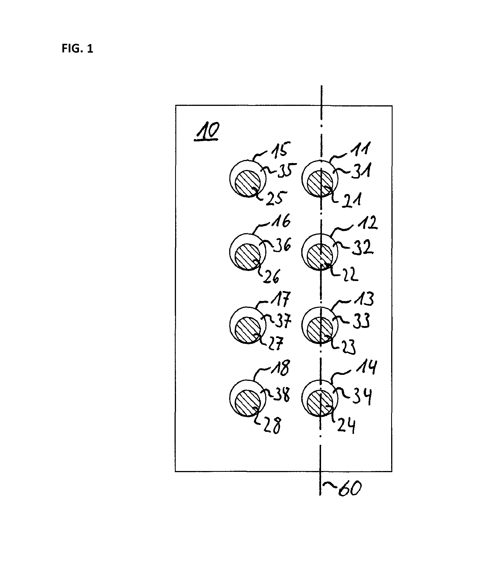
[0037]In FIG. 1 a preferred embodiment is shown. The fiber array is based on the substrate 10. Within the substrate holes 11, 12, 13, 14, 15, 16, 17 and 18 are provided. Fibers 21, 22, 23, 24, 25, 26, 27 and 28 are located within the corresponding holes or channels in the substrate 10. All fibers are located against the bottom side of the holes therefore leaving corresponding gaps 31, 32, 33, 34, 35, 36, 37 and 38.

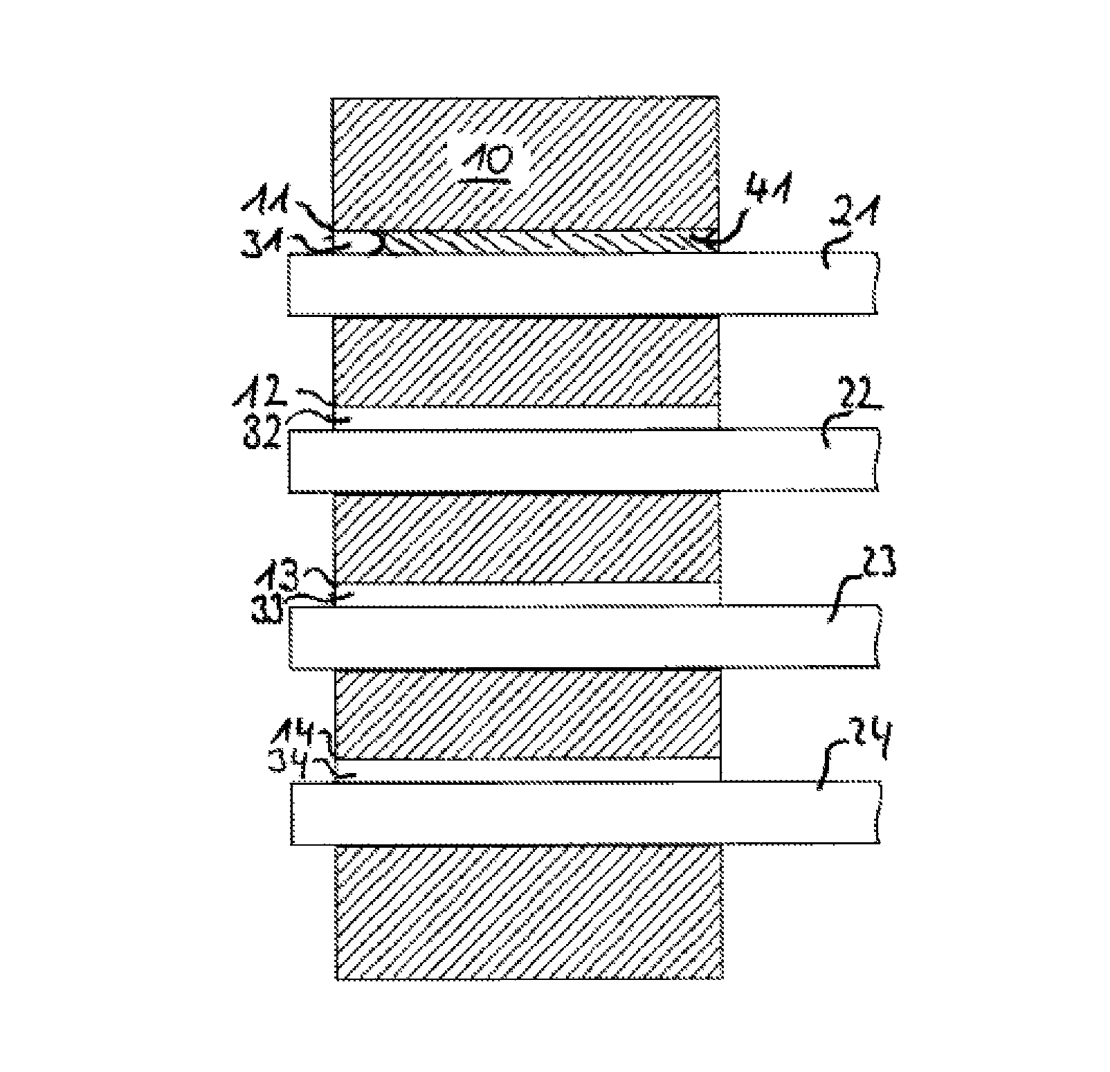
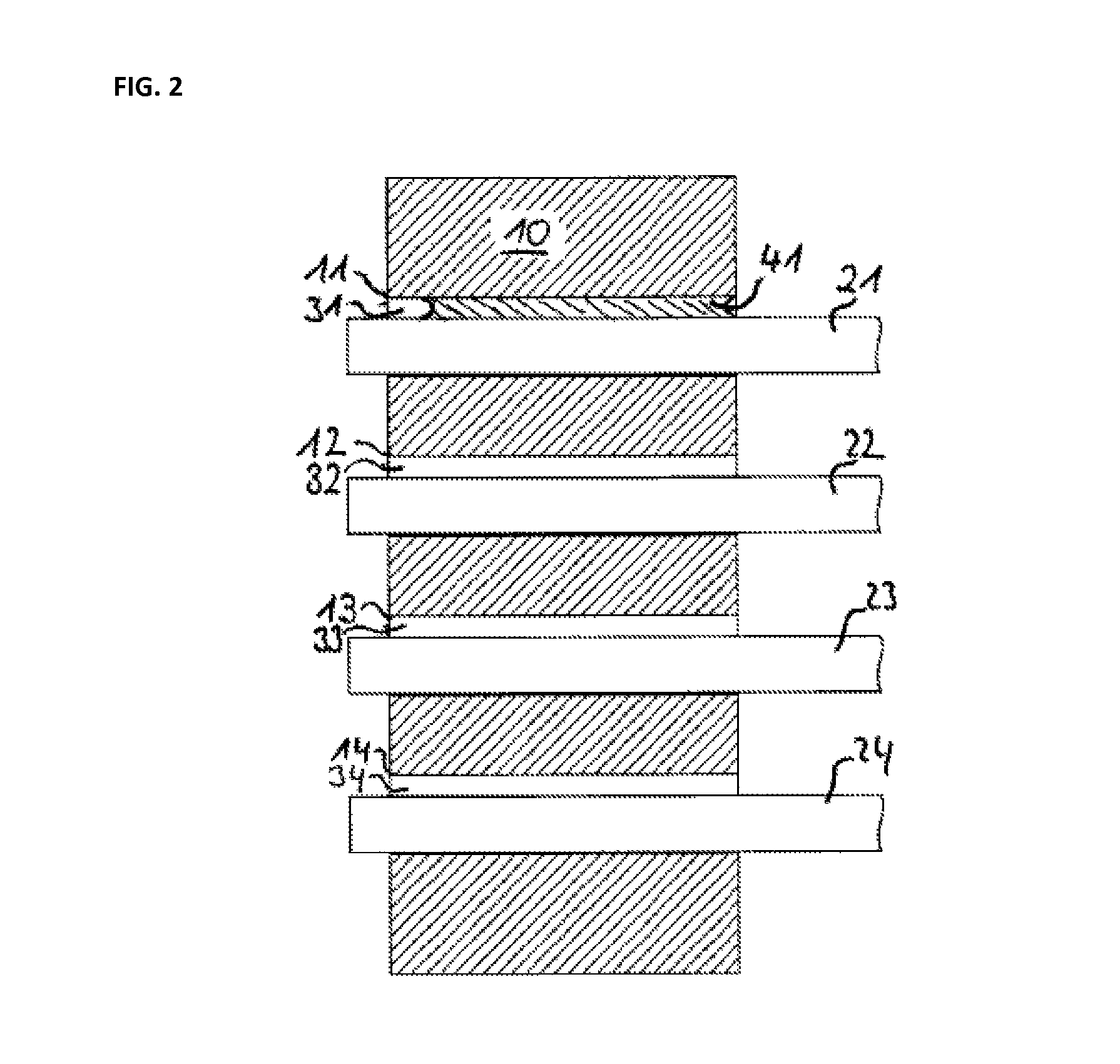
[0038]FIG. 2 shows a side cut view through sectional plane 60 of FIG. 1. Here again the fibers can be seen located against the bottom side of the holes (as viewed) and leaving corresponding gaps above the fibers. Here the fibers are axially parallel to their corresponding holes. Furthermore gap 31 of hole 11 is filled with glue 41. The other gaps may be filled accordingly. Here the other fibers are shown before they are glued into the holes. There is an excess fiber length at the left side which will be reduced to the same plane as the substrate by polishing.

[0039]FIG. 3 s...


PUM

PropertyMeasurementUnit
lengthaaaaaaaaaa
lengthsaaaaaaaaaa
transverse dimensionaaaaaaaaaa

Abstract

A collimator system comprises a micro lens array and a fiber array. The fiber array has a substrate with a plurality of holes for holding a plurality of optical fibers. The fibers are glued into the holes. Before gluing, each of the fibers is positioned against the same side of a corresponding hole resulting in all fibers being located substantially equally with respect to the holes. The lens array is mounted with an offset to the fiber array resulting in alignment of the fibers and the lenses.

Description

CROSS-REFERENCE TO RELATED APPLICATIONS[0001]This application claims priority from European Patent Application No. 11178443.5 filed on 23 Aug. 2011, the entire disclosure of which is incorporated herein by reference in its entirety.TECHNICAL FIELD[0002]The invention relates to a fiber optic collimator system, an, in particular, to such system for use in optical rotary joints, optical rotary joints, fiber arrays, and a method for manufacturing a fiber collimator array and a fiber array.BACKGROUND ART[0003]Multichannel optical rotary joints are often using a derotating optical element to compensate for the movement between the rotating parts. Such a derotating optical element may include a Dove prism or an Abbe-Koenig prism. In most cases light is transmitted by using optical fibers such as, for example, glass fibers or plastic fibers. For coupling the light from the optical fibers into and out of the derotating optical elements, collimators are used.[0004]U.S. Pat. No. 5,371,814 disc...

Claims


Application Information

Patent Timeline
Patent Type & Authority Patents(United States)
IPC IPC(8): G02B6/26G02B6/32G02B6/36
CPCG02B6/322G02B6/32G02B6/3604G02B6/3664G02B6/3672
Inventor POPP, GREGOR
Owner SCHLEIFRING & APPBAU
Why Eureka
Try Eureka