

Resistively heated small planar filament
a technology of resistive heating and planar filament, which is applied in the manufacture of electric discharge tubes/lamps, discharge tubes luminescnet screens, electrode systems, etc., can solve the problem of less performance variability between devices, and achieve the effect of improving the precision of filament placement, reducing the number of filaments, and improving the quality of filaments
- Summary
- Abstract
- Description
- Claims
- Application Information
AI Technical Summary
Benefits of technology
Problems solved by technology
Method used
Image

Examples
Embodiment Construction
[0027]Reference will now be made to the exemplary embodiments illustrated in the drawings, and specific language will be used herein to describe the same. It will nevertheless be understood that no limitation of the scope of the invention is thereby intended. Alterations and further modifications of the inventive features illustrated herein, and additional applications of the principles of the inventions as illustrated herein, which would occur to one skilled in the relevant art and having possession of this disclosure, are to be considered within the scope of the invention.
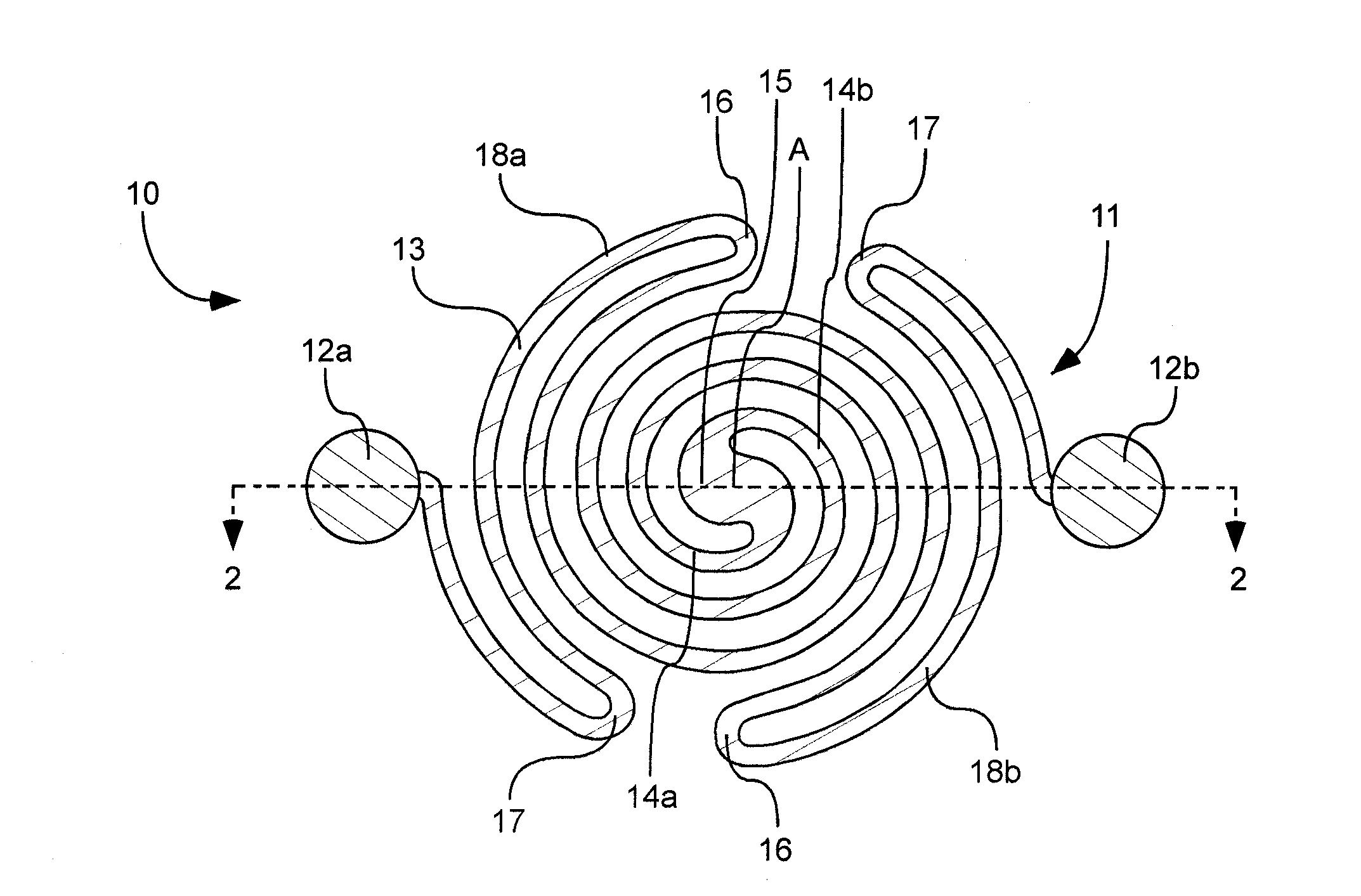
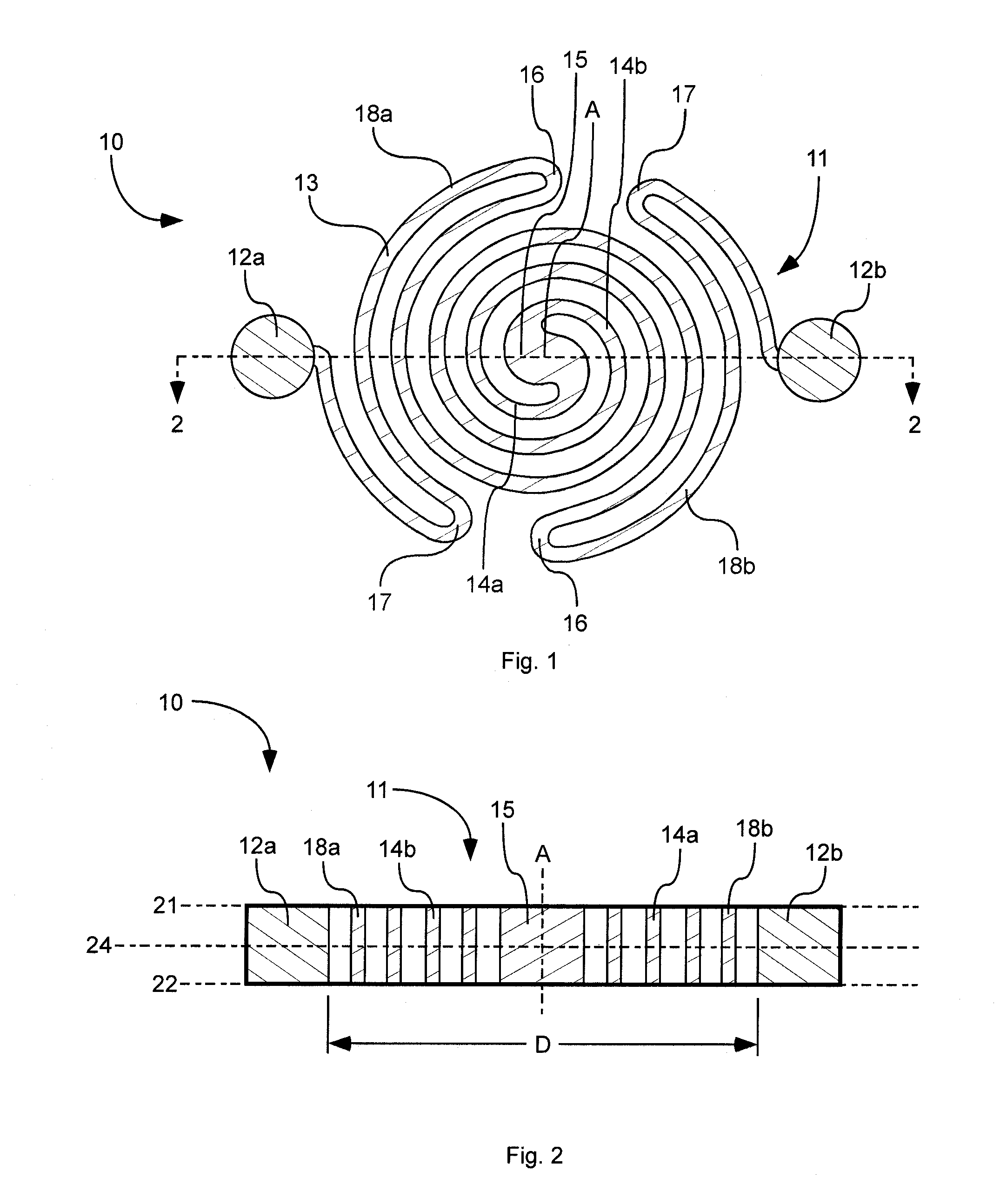
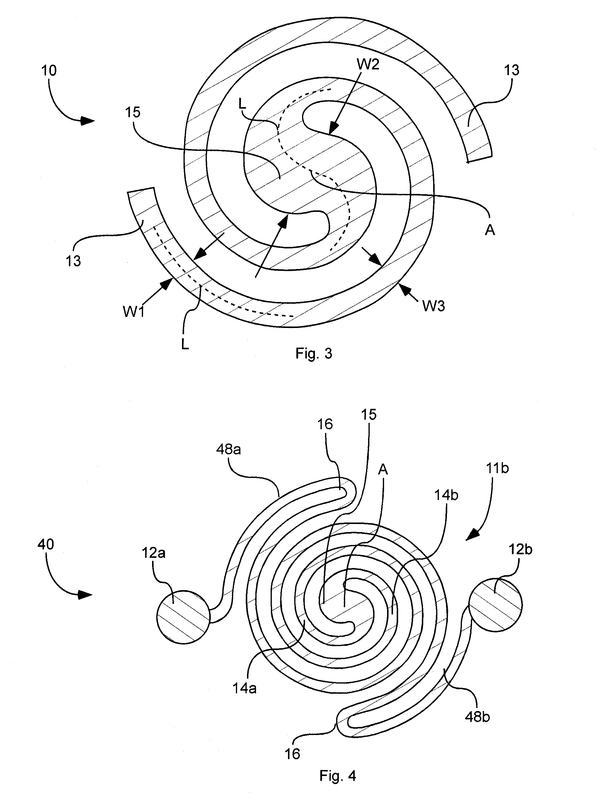
[0028]As shown in FIGS. 1-3, an electron emitter or filament device 10 is shown comprising a pair of spaced-apart bonding pads 12a-b and an elongated planar filament 11 extending between the pair of bonding pads 12a-b in a planar layer. The bonding pads 12a-b are configured to receive an electrical connection, such as being made of a shape and material that will allow for an electrical connection. The planar fila...
PUM
 Abstract
Description
Claims
Application Information