
Active edge grip rest pad

a technology of active edge and support plate, which is applied in the direction of hoisting equipment, charge manipulation, furnace, etc., can solve the problems of contaminating the wafer and damage the wafer, and achieve the effects of low profile, reduced overall height of the support plate, and easy measurement and inspection

Active Publication Date: 2007-11-06
BOOKS AUTOMATION US LLC
View PDF22 Cites 407 Cited by
  • Summary
  • Abstract
  • Description
  • Claims
  • Application Information

AI Technical Summary

Benefits of technology

This design ensures precise and repeatable placement of wafers, reduces contamination, and improves handling of wafers with varying edge radii, enhancing the reliability and cleanliness of wafer transfer processes.

Problems solved by technology

Sliding the wafer on a rest pad generates particulates which may contaminate the wafer.
The inside corner of a conventional distal rest pad traps particles between the wafer and the rest pad, which potentially may damage the wafer.

Method used


Image

  • Active edge grip rest pad
  • Active edge grip rest pad
  • Active edge grip rest pad

Examples


Embodiment Construction

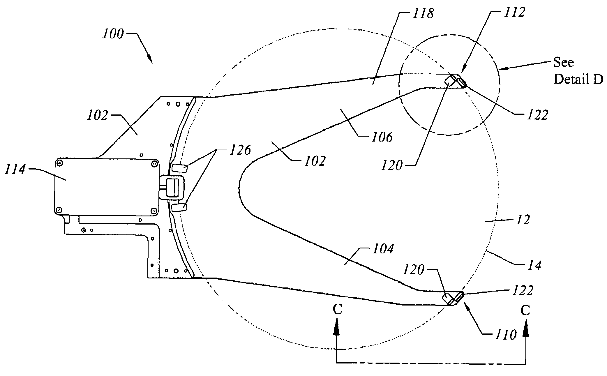
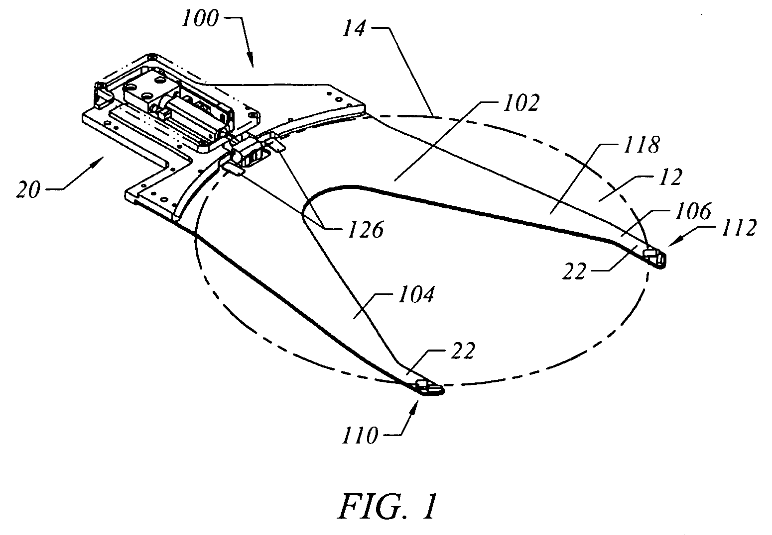
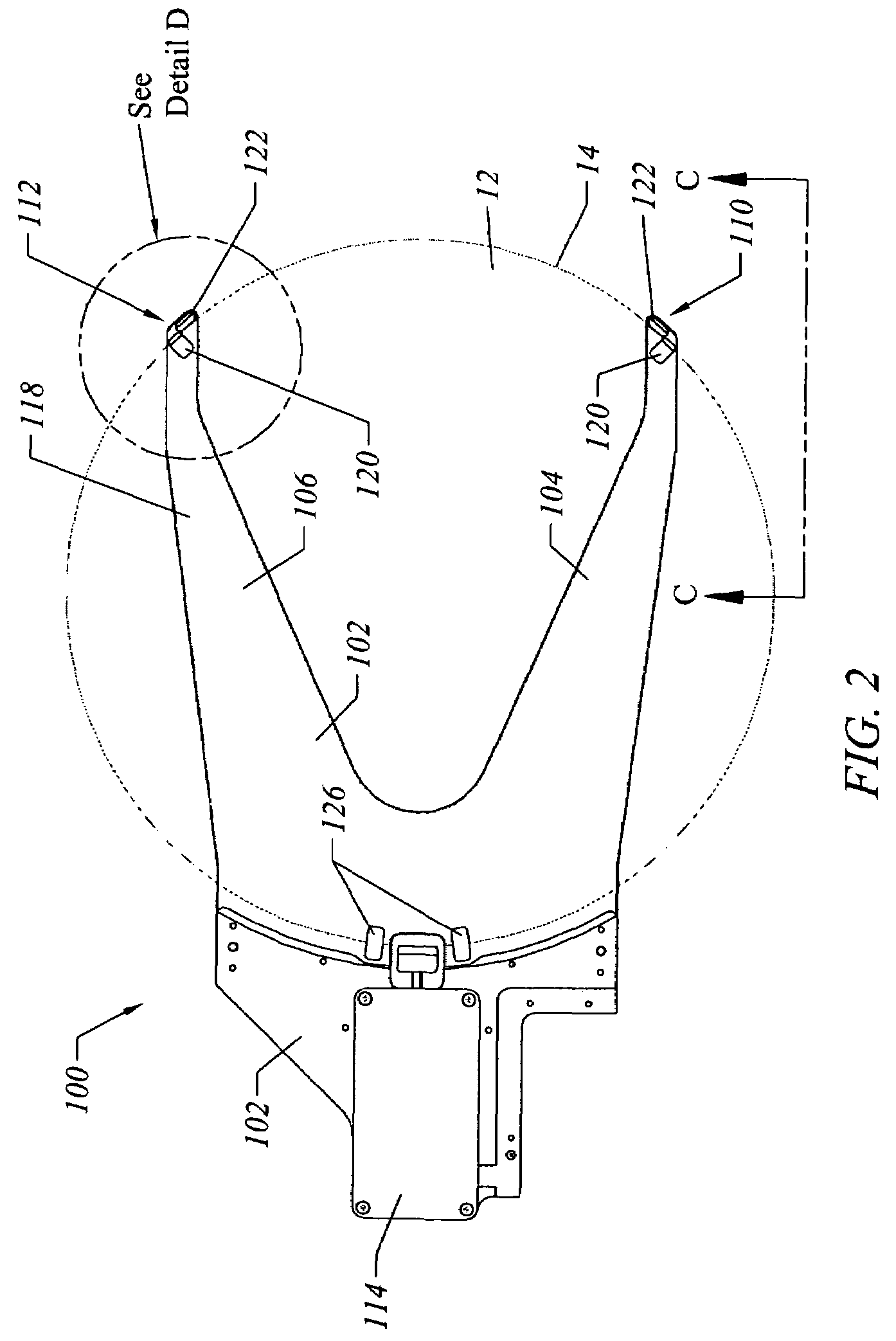
[0029]FIGS. 1-2 illustrate an embodiment of an end effector. The end effector 100 generally comprises a support plate 102 having a first finger 104 and a second finger 106 located at a distal end 110 of the support plate 102. Mounting holes are located throughout the support plate 102. As will be discussed in more detail later, each mounting hole is adapted to receive a specific element (e.g., distal rest pad, proximal rest pad, etc.). The end effector 100 shown in FIGS. 1-2 is merely an example and the present invention is not limited for use with this specific configuration.

[0030]The end effector 100 is configured to support and transport a wafer 12. In order to support a wafer 12, the end effector 100 includes, among other things, a first distal rest pad 110 and a second distal rest pad 112, a pair of proximal rest pads 126, and a pusher device 114. The pusher device 114 urges a wafer 12 seated on the support plate 102 towards the first distal rest pad 110 and the second distal r...


PUM


Abstract

The present invention comprises a distal rest pad for supporting a portion of a wafer seated on an end effector. In one embodiment, the rest pad includes a bottom support pad and an edge stop. Each element is mounted separately to the distal end of a support plate. The bottom support pad includes an inclined surface that transitions to a substantially horizontal surface at its distal end. The edge stop has a substantially vertical wafer contact surface that the peripheral edge of a wafer eventually contacts as the wafer is urged towards the distal rest pad. In another embodiment, the bottom support pad comprises an inclined surface. In yet another embodiment, the distal rest pad comprises a single structure. This distal rest pad includes a backstop portion and a bottom support separated by a particle collection groove. The bottom support may include an inclined lead-in surface that transitions into a flat contact surface or only comprise an inclined lead-in surface.

Description

FIELD OF THE INVENTION[0001]The present invention generally relates to end effectors for supporting and transporting semiconductor wafers. More specifically, the present invention is a distal rest pad for supporting a portion of a wafer.BACKGROUND[0002]Conventional edge grip end effectors have wafer grip pads with included angles that create problems solved by this invention. Conventional distal rest pads often have an inside corner into which the edge of the wafer is urged by a rear pusher to mechanically retain the wafer on the end effector.[0003]FIG. 1 illustrates an embodiment of a spatula-shaped end effector 10 of this invention for transferring semiconductor wafers, such as a wafer 12 (shown transparent to reveal underlying structures), to and from a wafer cassette (not shown). End effector 10 is adapted to receive and securely hold wafer 12 and transfer it to and from a cassette for processing. Wafers having diameters of less than 150 mm are typically spaced apart at a 4.76 m...

Claims


Application Information

Patent Timeline
Patent Type & Authority Patents(United States)
IPC IPC(8): B65G49/07
CPCH01L21/68707Y10S414/141Y10S294/902
Inventor BONORA, ANTHONY C.HINE, ROGER G.NOBLES, JR., D. WAYNERILEY, NORMA B.
Owner BOOKS AUTOMATION US LLC
Learn More