Precision two-dimensional fiber-collimator-array
- Summary
- Abstract
- Description
- Claims
- Application Information
AI Technical Summary
Benefits of technology
Problems solved by technology
Method used
Image
Examples
Embodiment Construction
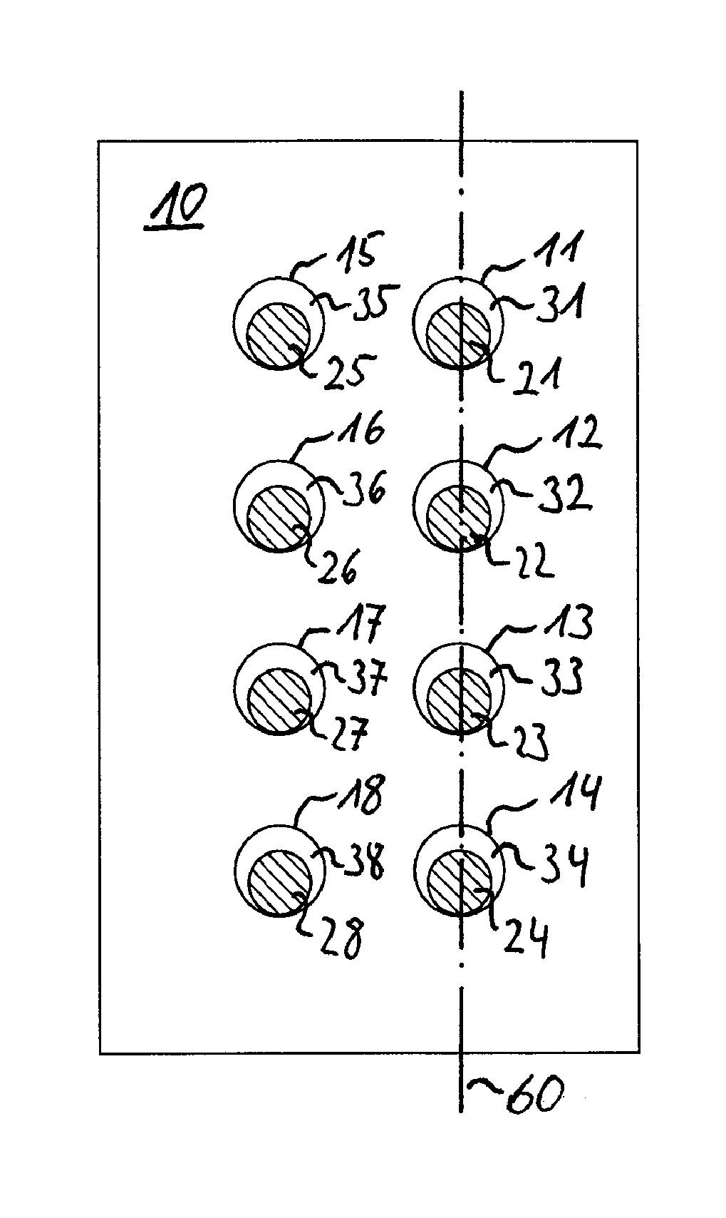
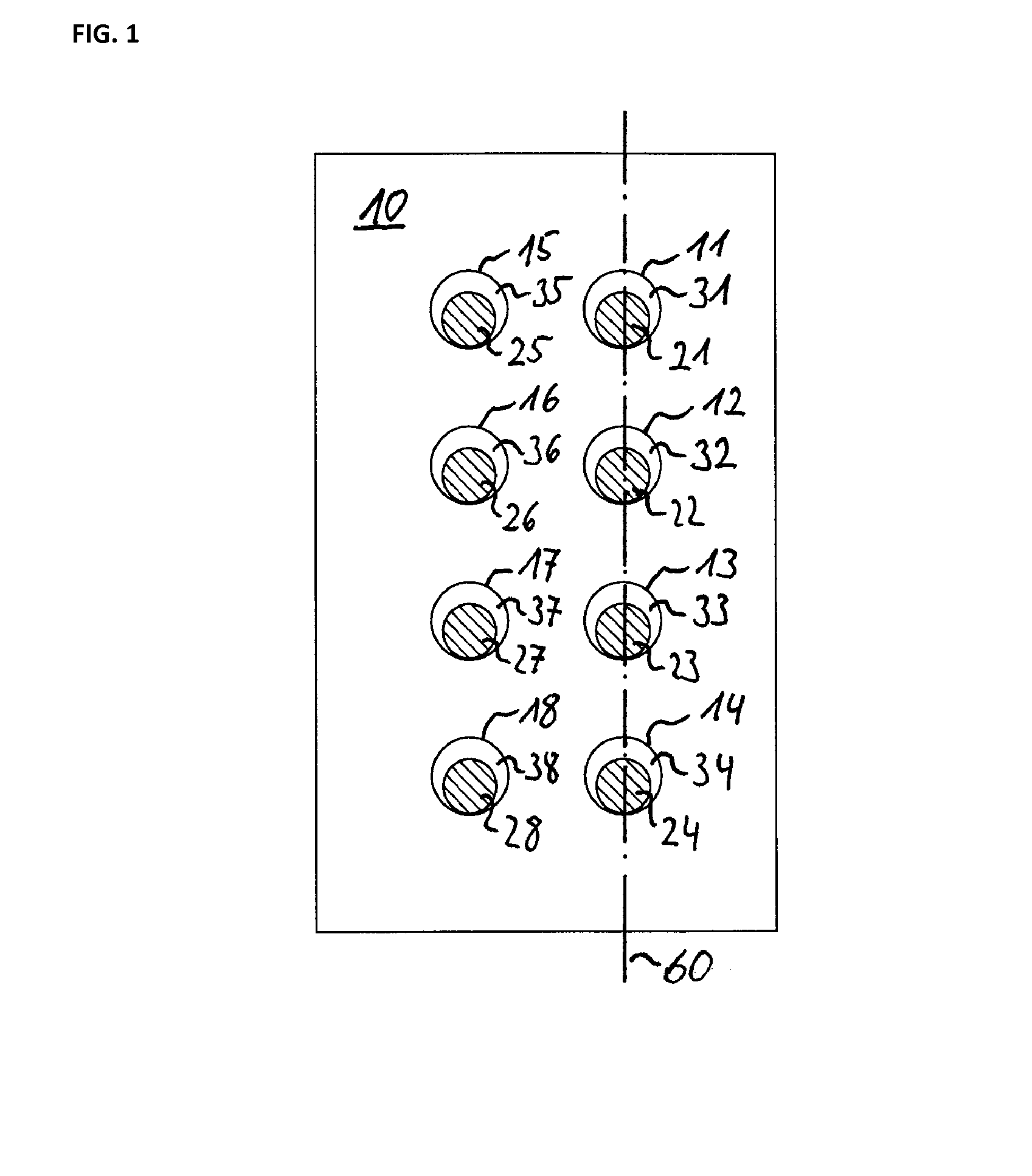
[0037]In FIG. 1 a preferred embodiment is shown. The fiber array is based on the substrate 10. Within the substrate holes 11, 12, 13, 14, 15, 16, 17 and 18 are provided. Fibers 21, 22, 23, 24, 25, 26, 27 and 28 are located within the corresponding holes or channels in the substrate 10. All fibers are located against the bottom side of the holes therefore leaving corresponding gaps 31, 32, 33, 34, 35, 36, 37 and 38.
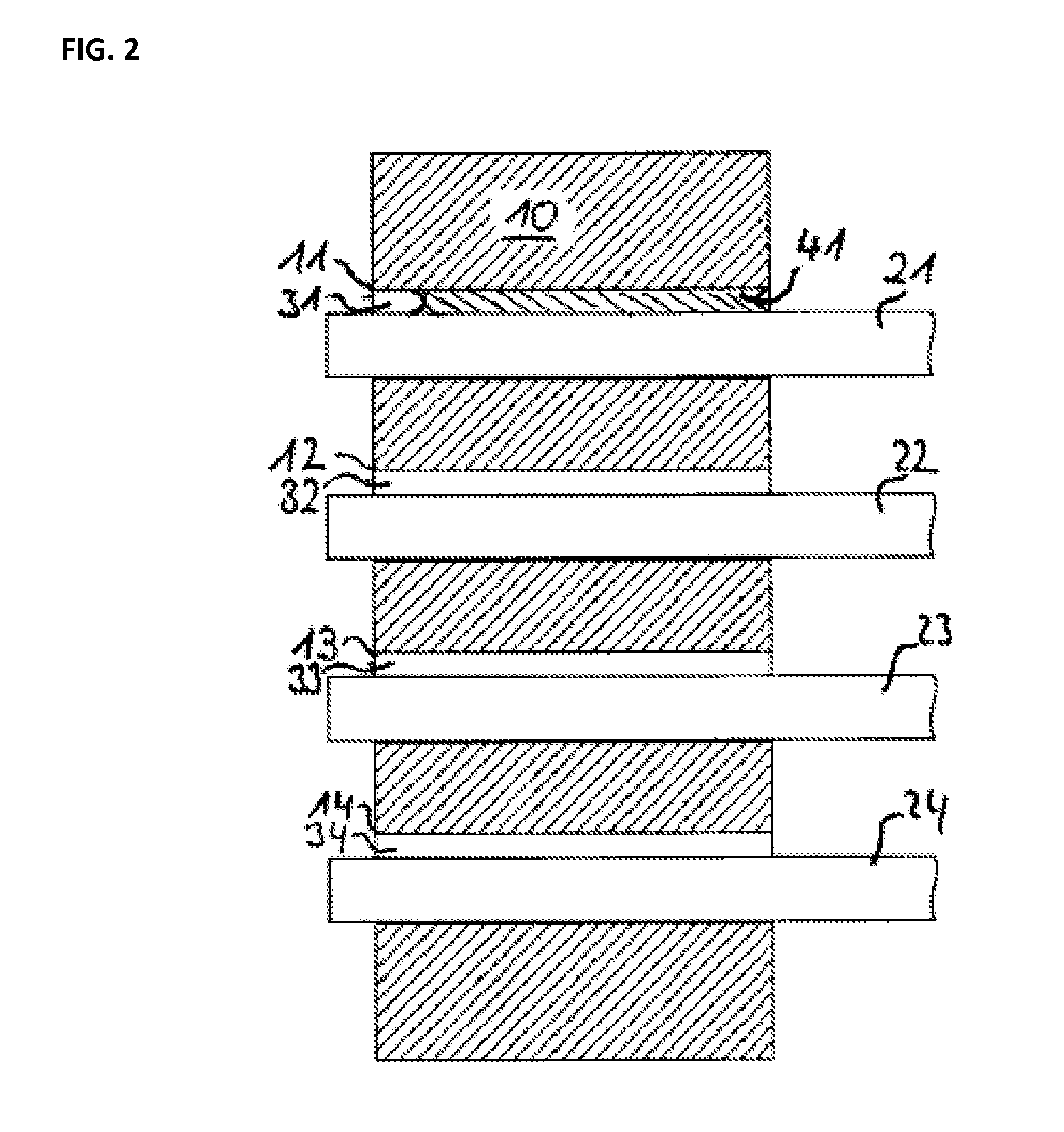
[0038]FIG. 2 shows a side cut view through sectional plane 60 of FIG. 1. Here again the fibers can be seen located against the bottom side of the holes (as viewed) and leaving corresponding gaps above the fibers. Here the fibers are axially parallel to their corresponding holes. Furthermore gap 31 of hole 11 is filled with glue 41. The other gaps may be filled accordingly. Here the other fibers are shown before they are glued into the holes. There is an excess fiber length at the left side which will be reduced to the same plane as the substrate by polishing.
[0039]FIG. 3 s...
PUM
| Property | Measurement | Unit |
|---|---|---|
| Length | aaaaa | aaaaa |
Abstract
Description
Claims
Application Information
 - R&D
- Intellectual Property
- Life Sciences
- Materials
- Tech Scout
- Unparalleled Data Quality
- Higher Quality Content
- 60% Fewer Hallucinations
Browse by: Latest US Patents, China's latest patents, Technical Efficacy Thesaurus, Application Domain, Technology Topic, Popular Technical Reports.
© 2025 PatSnap. All rights reserved.Legal|Privacy policy|Modern Slavery Act Transparency Statement|Sitemap|About US| Contact US: help@patsnap.com


