A sample collection device that automatically enters and exits a sample storage barrel

A technology for sample collection and sample storage buckets, applied in the direction of analysis materials, instruments, etc., can solve problems such as affecting sample test results and production and operation, low production efficiency of collection devices, affecting production and operation of enterprises, etc., to avoid long-term exchange, shorten Effect of residence time, labor cost and production cost reduction

Active Publication Date: 2018-02-16
HUNAN SUNDY SCI & TECH DEV
View PDF4 Cites 0 Cited by
  • Summary
  • Abstract
  • Description
  • Claims
  • Application Information

AI Technical Summary

Problems solved by technology

[0005] (1) The intelligence level of the existing sample collection device is not high. When the sample storage barrels enter and leave the sample collection device, manual transfer is required. Before operation, each sample storage barrel must be installed in the sample collection device one by one. After the collection operation is completed, manpower is required to take each sample storage barrel out of the sample collection device one by one, which consumes a lot of human energy, leads to high labor costs, and is prone to safety accidents
[0006] (2) Due to the need to manually pick and place the sample barrels one by one, the existing sample collection device must be shut down before the pick-and-place operation, and the shutdown takes a long time, which makes the production efficiency of the existing sample collection device low and seriously affects Enterprise production and operation
[0007] (3) Due to the manual operation of taking and placing the sample barrels, it is easy to change the samples manually during the process of taking, placing and transferring, and it is prone to sample fraud, which will seriously affect the subsequent test results and production and operation of the samples

Method used


Image

  • A sample collection device that automatically enters and exits a sample storage barrel
  • A sample collection device that automatically enters and exits a sample storage barrel
  • A sample collection device that automatically enters and exits a sample storage barrel

Examples


Embodiment Construction

[0035] The present invention will be described in further detail below in conjunction with specific embodiments and accompanying drawings.

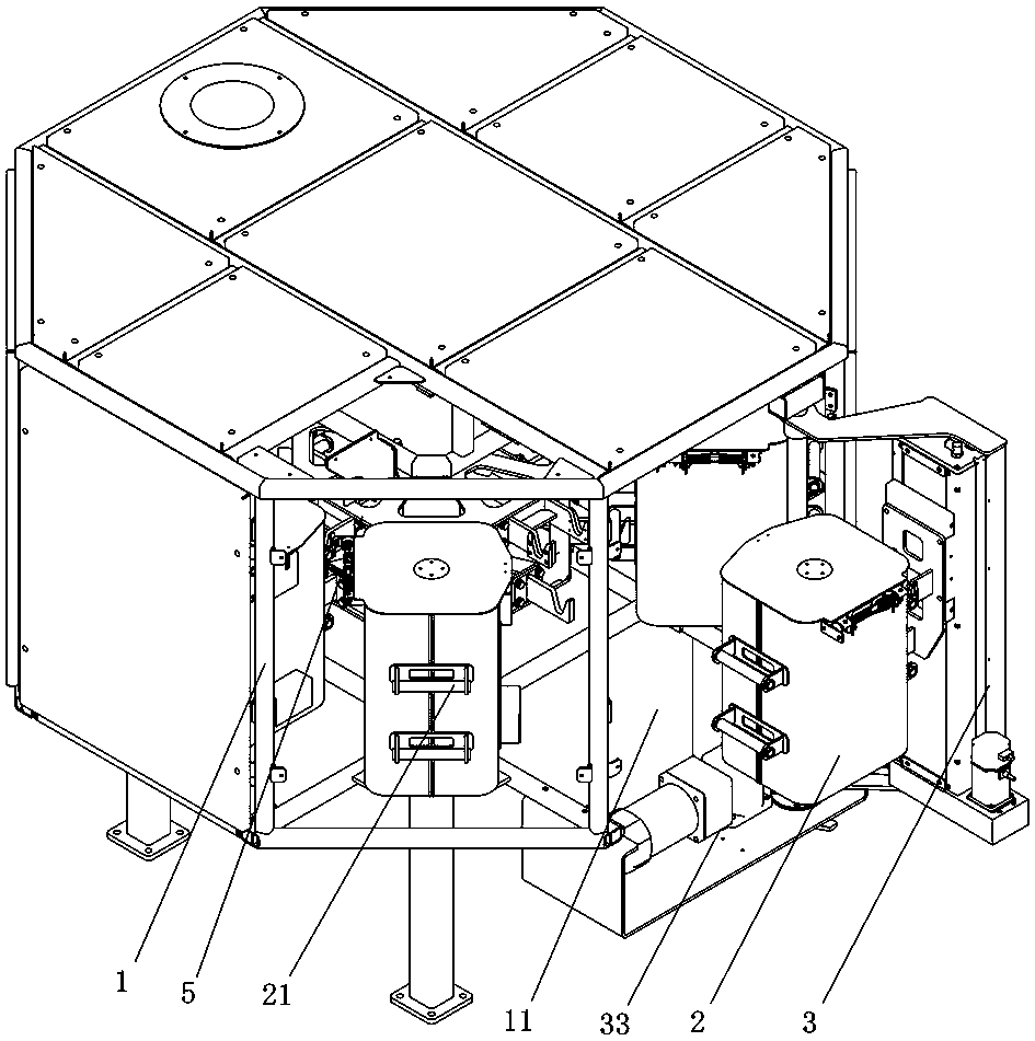
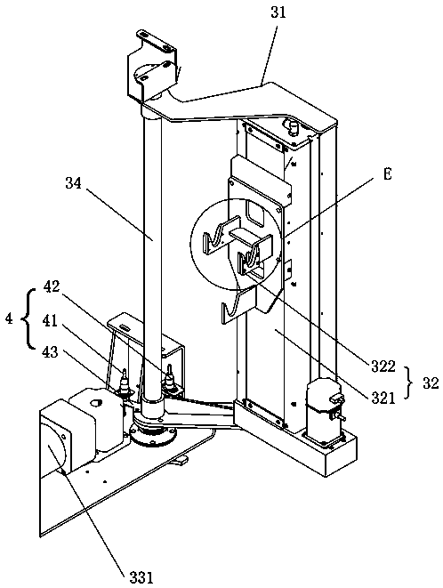
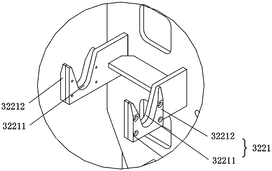
[0036] Such as Figure 1 to Figure 5 As shown, the present invention provides a sample collection device that automatically enters and exits the sample storage barrel, including a frame 1, and a plurality of sample storage barrels 2 are hung in the collection cavity formed by the frame 1, and the side of the frame 1 is provided with a storage tank. The sample barrel 2 enters and exits the inlet and outlet 11 of the sample collection device. An automatic barrel entry and exit mechanism 3 is provided at the entrance and exit 11. The automatic barrel entry and exit mechanism 3 includes a matching revolving door 31 and a hooking assembly 32. The revolving door 31 is located at the 11 entrances and exits. Rotate back and forth to complete the opening / closing of the inlet and outlet 11 (the revolving door 31 is equivalent to the revolving door of...


PUM


Abstract

The invention discloses a sample collecting device capable of automatically inputting or outputting sample storage barrels.The sample collecting device comprises a rack, and multiple sample storage barrels are hung in a collecting cavity formed by the rack; an input and output opening for inputting or outputting sample storage barrels from the sample collecting device is formed in the side face of the rack, an automatic barrel input and output mechanism is arranged on the input and output opening and comprises a rotating door and a hooking assembly which are matched, the rotating door rotates in a reciprocating mode on the input and output opening to complete opening/closing of the input and output opening, and the hooking assembly is arranged on the inner side of the rotating door and used for hooking one sample storage barrel and then automatically inputting or outputting the sample storage barrel through rotation of the rotating door.The sample collecting device has the advantages of being simple and compact in structure, high in intelligent degree, high in transfer safety of a sample storage station, high in working efficiency and low in production cost.

Description

technical field [0001] The invention mainly relates to equipment for collecting and processing material samples, in particular to a sample collecting device that automatically enters and exits a sample storage barrel. Background technique [0002] For the sampling, sample preparation, and testing of material (such as ore, coal) samples, each country has mandatory standards, and the sampling and processing of samples must be carried out in accordance with the standards. The principle of sample sampling, sample preparation, and testing work process is to gradually reduce the particle size and quality of the collected samples without destroying the representativeness of the sample, until it meets the particle size and quality of the sample in the laboratory test ( Weight) accuracy requirements, and then carry out relevant laboratory analysis on the samples that meet the requirements. [0003] For example, taking coal sampling as an example, it is actually a sampling and analys...

Claims


Application Information

Patent Timeline
Patent Type & Authority Patents(China)
IPC IPC(8): G01N35/04
CPCG01N35/04G01N2035/00207G01N2035/0446
Inventor 龚伟业唐建国谭为
Owner HUNAN SUNDY SCI & TECH DEV
Why Eureka
Try Eureka