
Cover assemblies, kits and methods for covering electrical cables and connections

a technology for electrical cables and covers, applied in the direction of electrical cable installations, cable junctions, cable fittings, etc., can solve the problems of crippling power outage, loss of life, and critical maintenance of cable integrity

Active Publication Date: 2016-11-22
TYCO ELECTRONICS CANADA +1
View PDF14 Cites 21 Cited by
  • Summary
  • Abstract
  • Description
  • Claims
  • Application Information

AI Technical Summary

Benefits of technology

The invention is a cover assembly for protecting and insulating electrical connections. It includes a joint body with an inner sleeve and an integral semiconductor layer. The inner sleeve is made of elastically expandable material and has an outer surface with two terminal ends. The semiconductor layer is made of electrically semiconductive material and extends from one terminal end to the other. The semiconductor layer has a prescribed distance from the inner sleeve, creating a tubular band on the outer surface that is not covered by the semiconductor layer. The cover assembly is mounted on the cables to protect the connection. The technical effect of this invention is to provide a reliable and efficient way to protect and insulate electrical connections.

Problems solved by technology

In the electrical utilities industry, maintaining cable integrity may be critical.
A loss of cable integrity, for example, a short circuit in a high voltage cable, may result in a crippling power outage or, even worse, a loss of life.
One everyday task that may pose a great threat to cable integrity is the formation of electrical connections.
If the connection was energized without rebuilding the cable layers, the metallic connection may fail immediately or very soon after.

Method used

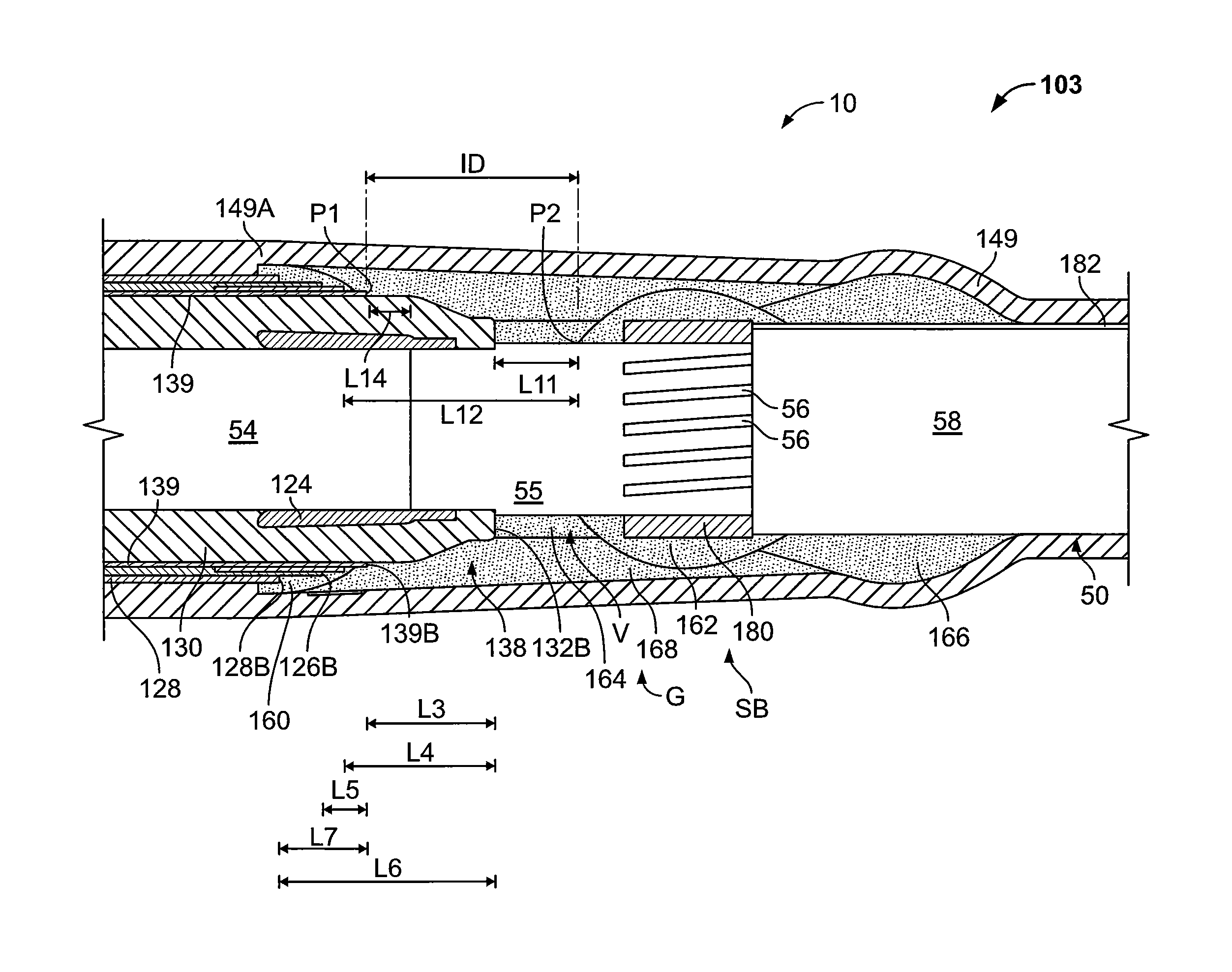
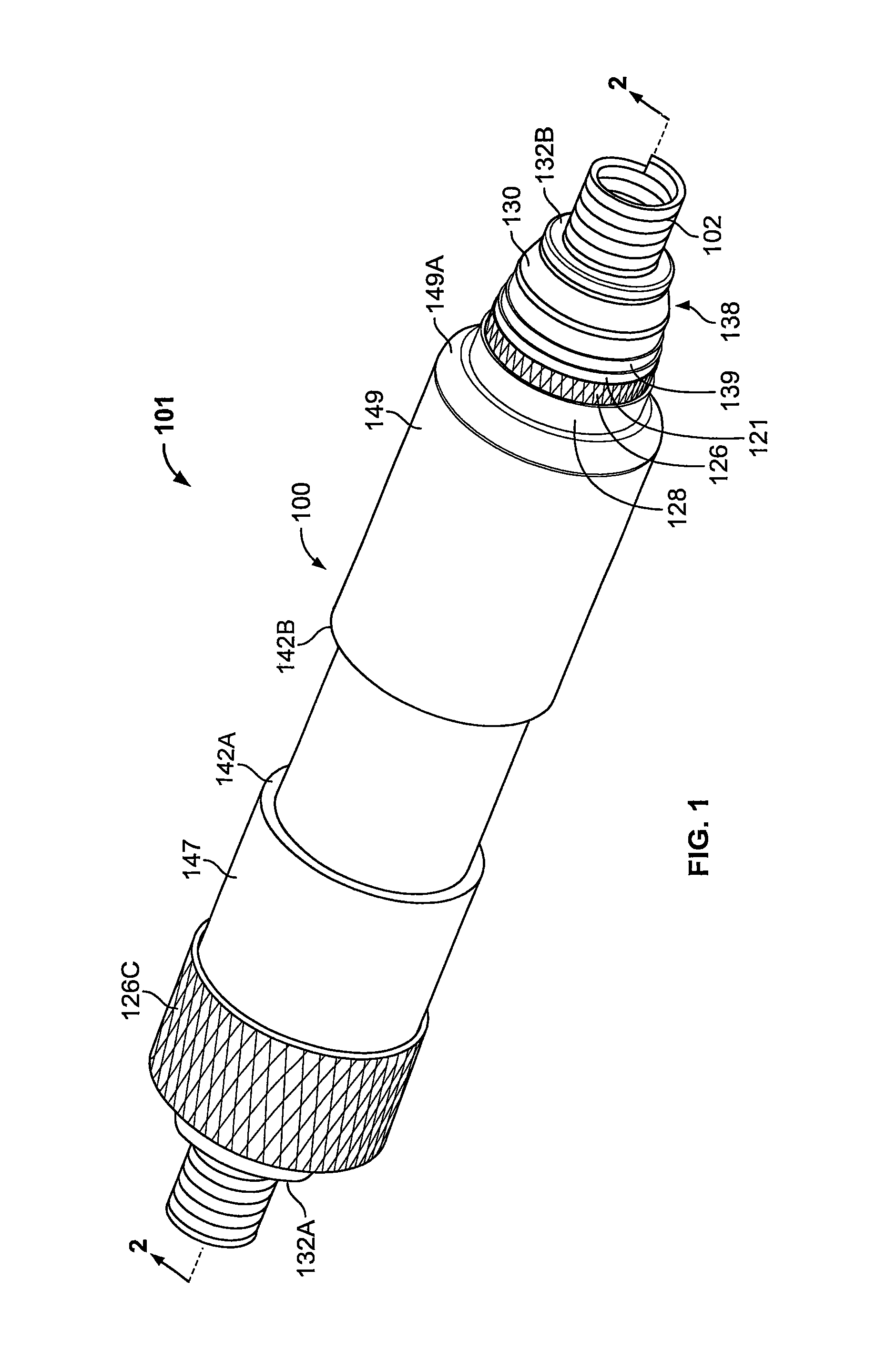
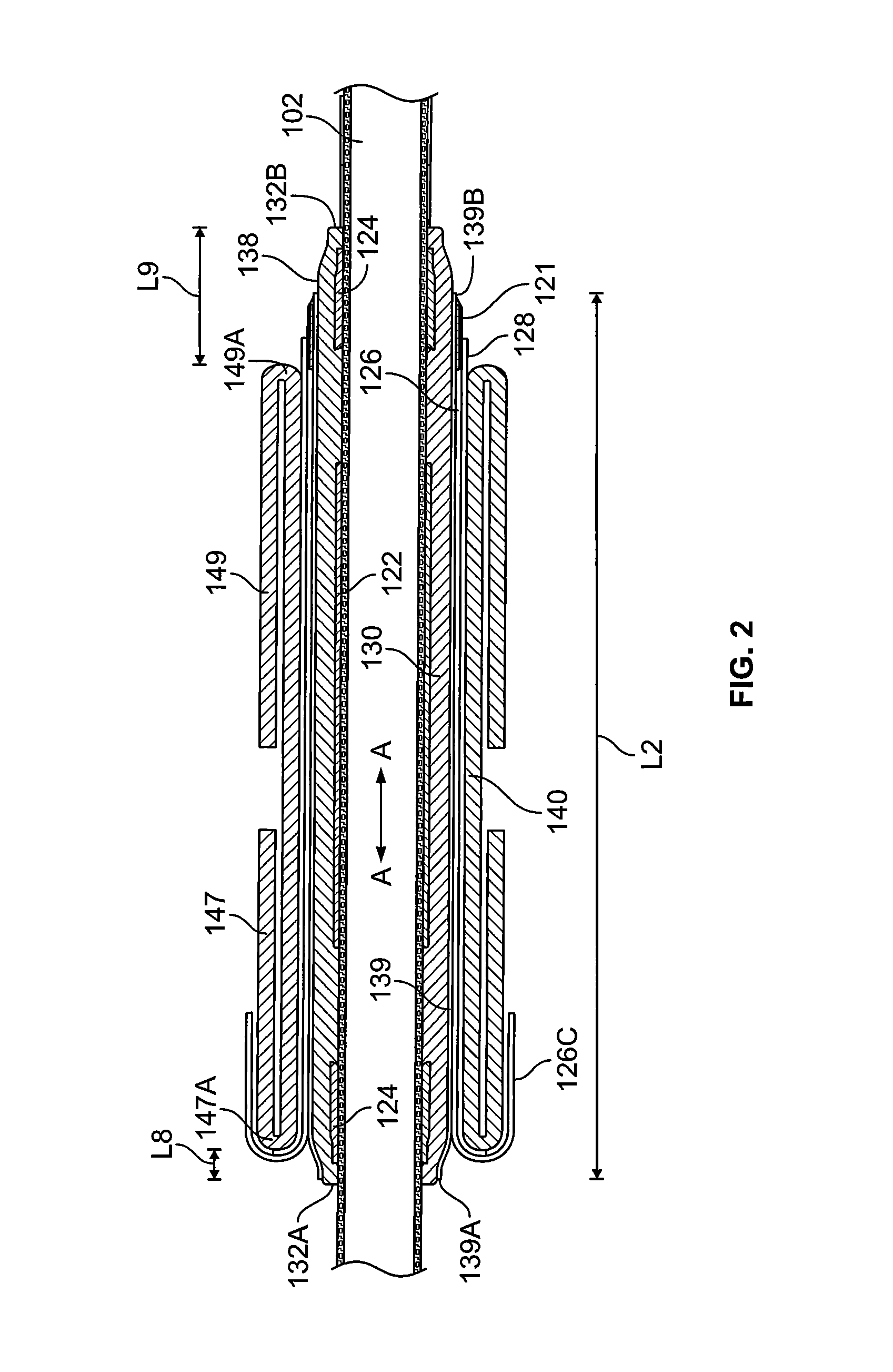

Image

  • Cover assemblies, kits and methods for covering electrical cables and connections
  • Cover assemblies, kits and methods for covering electrical cables and connections
  • Cover assemblies, kits and methods for covering electrical cables and connections

Examples


Embodiment Construction

[0016]The present invention now will be described more fully hereinafter with reference to the accompanying drawings, in which illustrative embodiments of the invention are shown. In the drawings, the relative sizes of regions or features may be exaggerated for clarity. This invention may, however, be embodied in many different forms and should not be construed as limited to the embodiments set forth herein; rather, these embodiments are provided so that this disclosure will be thorough and complete, and will fully convey the scope of the invention to those skilled in the art.

[0017]It will be understood that, although the terms first, second, etc. may be used herein to describe various elements, components, regions, layers and / or sections, these elements, components, regions, layers and / or sections should not be limited by these terms. These terms are only used to distinguish one element, component, region, layer or section from another region, layer or section. Thus, a first elemen...


PUM

PropertyMeasurementUnit
elongationaaaaaaaaaa
thicknessaaaaaaaaaa
lengthaaaaaaaaaa

Abstract

A cover assembly for covering and electrically insulating an electrical connection includes a joint body including a tubular inner sleeve and an integral semiconductor layer. The inner sleeve is formed of an elastically expandable, electrically insulating material and having an outer surface and opposed first and second terminal ends. The inner sleeve defines a through passage extending axially from a first end opening at the first terminal end of the inner sleeve to a second terminal end opening at the second end of the inner sleeve. The semiconductor layer is disposed on the outer surface of the inner sleeve and is formed of an electrically semiconductive material. The semiconductor layer extends axially from a first terminal end of the semiconductor layer to an opposing second terminal end of the semiconductor layer. The first terminal end of the semiconductor layer is spaced apart from the first terminal end of the inner sleeve a prescribed semiconductor truncation distance to define a tubular band of the outer surface that is not covered by the semiconductor layer.

Description

RELATED APPLICATION(S)[0001]The present application claims the benefit of and priority from U.S. Provisional Patent Application No. 61 / 994,341, filed May 16, 2014, the disclosure of which is incorporated herein by reference in its entirety.FIELD OF THE INVENTION[0002]The present invention relates to electrical cables and connections and, more particularly, to protective covers for electrical cables and electrical connections.BACKGROUND OF THE INVENTION[0003]In the electrical utilities industry, maintaining cable integrity may be critical. A loss of cable integrity, for example, a short circuit in a high voltage cable, may result in a crippling power outage or, even worse, a loss of life. One everyday task that may pose a great threat to cable integrity is the formation of electrical connections.[0004]When electrical connections are formed, a bare metal surface may be exposed such as a splice connector. If the connection is made between two insulated cables, it is assumed the connect...

Claims


Application Information

Patent Timeline
Patent Type & Authority Patents(United States)
IPC IPC(8): H02G15/184H02G15/18H05K9/00
CPCH05K9/0088H02G15/184H02G15/1833H05K9/0007Y10T29/49197
Inventor DINU, DANIELYAWORSKI, HARRYKENNEDY, SEANSERAJ, MAHMOUD
Owner TYCO ELECTRONICS CANADA
Learn More