Hair styling device

a technology for styling devices and hair, applied in curling-tongs, curling-irons, hair cleaning, etc., can solve problems such as poor gliding, and achieve the effect of less travel

Inactive Publication Date: 2016-11-29
KONINKLJIJKE PHILIPS NV
View PDF14 Cites 0 Cited by
  • Summary
  • Abstract
  • Description
  • Claims
  • Application Information

AI Technical Summary

Benefits of technology

[0006]In a hair straightener with resiliently mounted heating plates, when the two jaws (or arms) are fully closed, the distal ends of the heating plates will touch while the proximal ends will reserve a gap as at their proximal ends, the heating plates can still move as a result of their being resiliently mounted. The notions “distal” and “proximal” are to be understood as viewed from a hinge of the hair straightener. The maximum width of the gap at the proximal ends of the heating plates in this fully closed situation is preferably within a range of 1 mm-1.5 mm to obtain good gliding results and to have a sufficiently tight clamping of the hair.
[0008]One embodiment of the present invention provides a mechanism which controls the proximal end of the floating heat plate with less travel during “no sleeve situation”, such that the proximal gap can maintain 1 mm which fulfills the preferred width of 1 mm-1.5 mm.

Problems solved by technology

For example, if the “with sleeve situation” is designed such that the desired design requirement is fulfilled, such that the rear gap is e.g. 1 mm in closed position, then the rear gap in the “no sleeve situation” will become 2.4 mm, which causes a poor gliding result.

Method used


Image

  • Hair styling device
  • Hair styling device
  • Hair styling device

Examples


Embodiment Construction

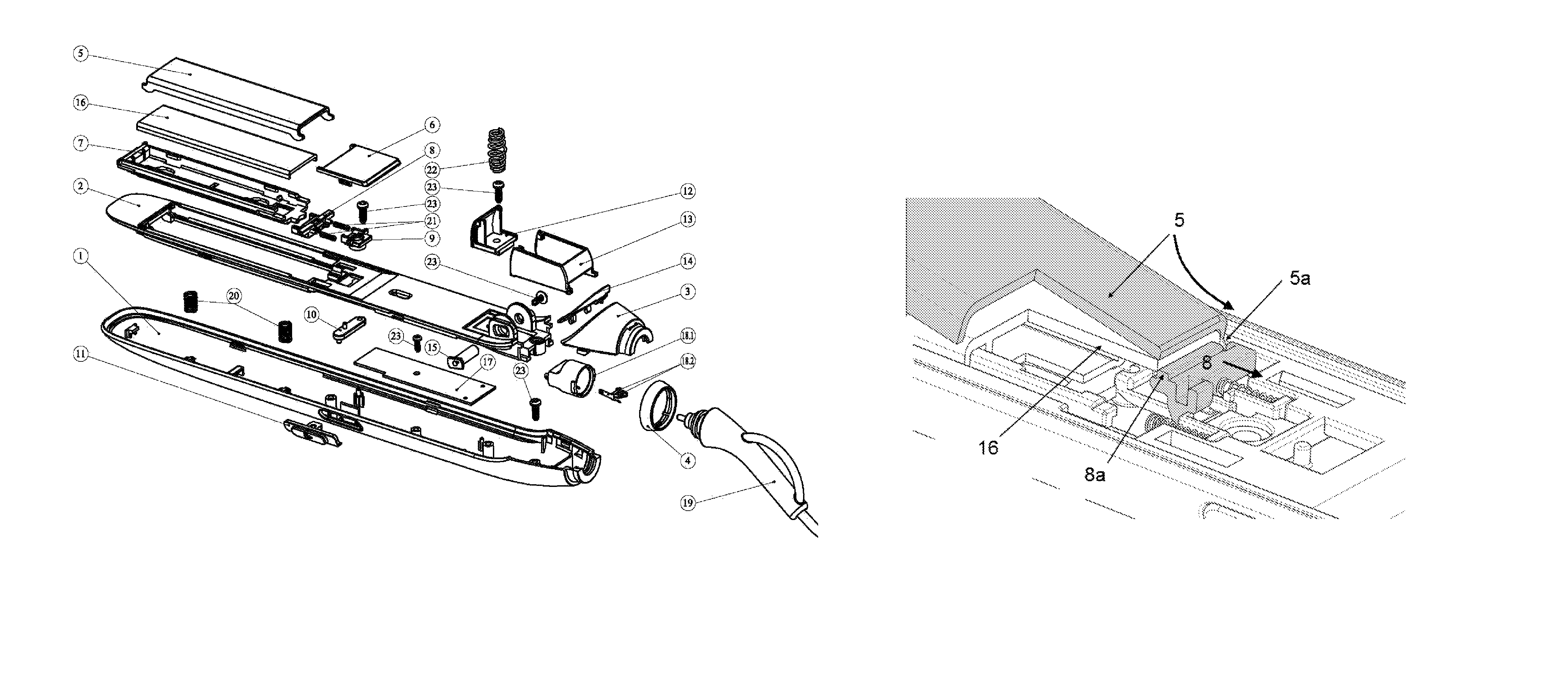
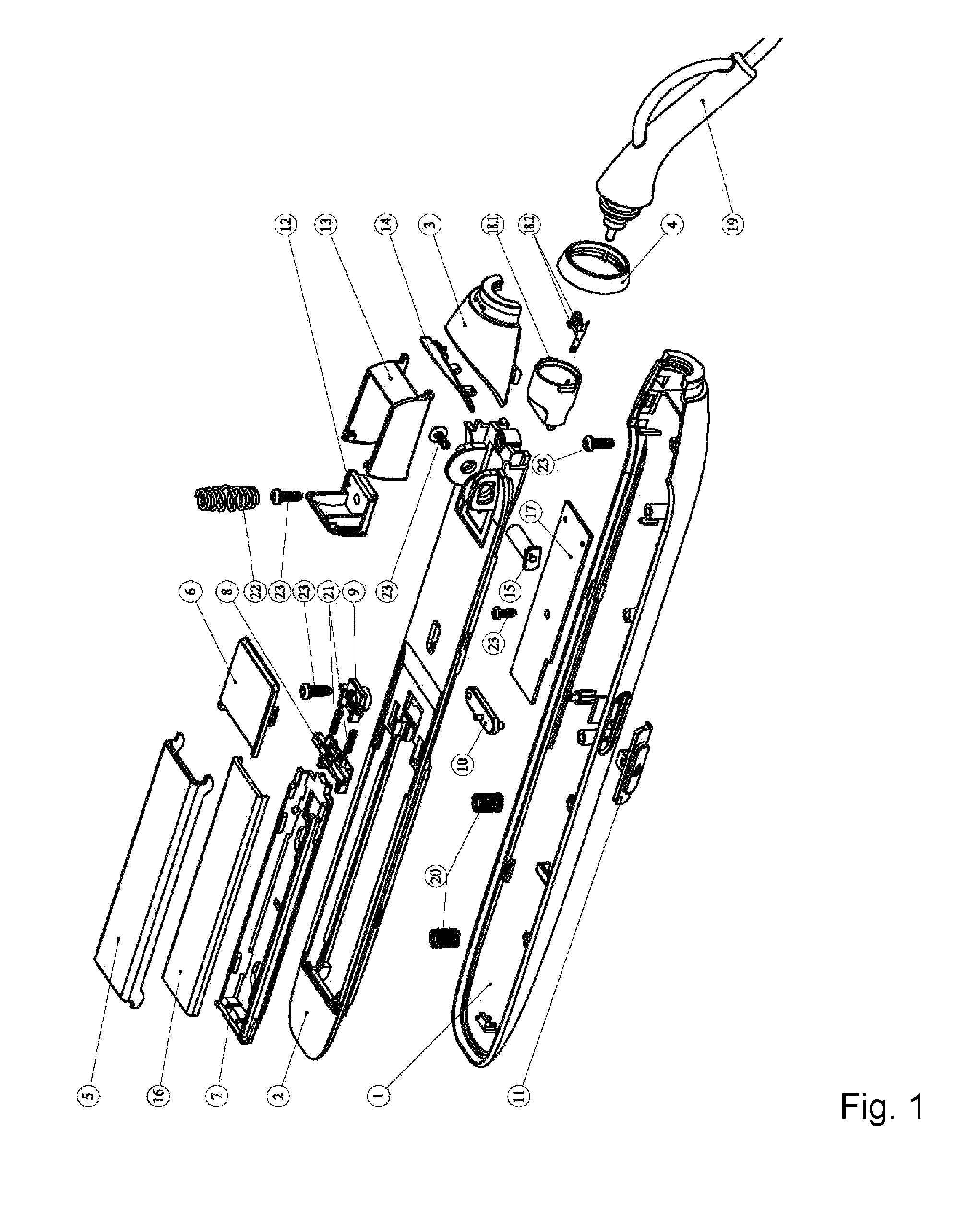
[0017]In the exploded view of FIG. 1, the reference signs have the following meanings:[0018]1 housing, lower part[0019]2 inner housing cover, lower part[0020]3 end cover[0021]4 lock ring[0022]5 detachable holder with a hair treatment agent, in this embodiment a sleeve[0023]6 sleeve sliding cover[0024]7 heat resistant frame[0025]8 unit capable of engaging the detachable holder 5, in this embodiment a sleeve release bracket[0026]9 fixing plate[0027]10 lower lever[0028]11 lower sleeve switch cover[0029]12, 13 hinge cover parts[0030]14 decoration plate[0031]15 shaft[0032]16 heating plate[0033]17 printed circuit board assembly[0034]18.1, 18.2 swivel contact plate[0035]19 power cord[0036]20, 21, 22 springs[0037]23 tapping screws.

[0038]As shown in FIG. 1, the straightener has an extended function wherein an accessory, a sleeve 5, can be attached to the heating plate 16. The sleeve 5 contains active ingredients that will be released to the hair during the straightening of hair.
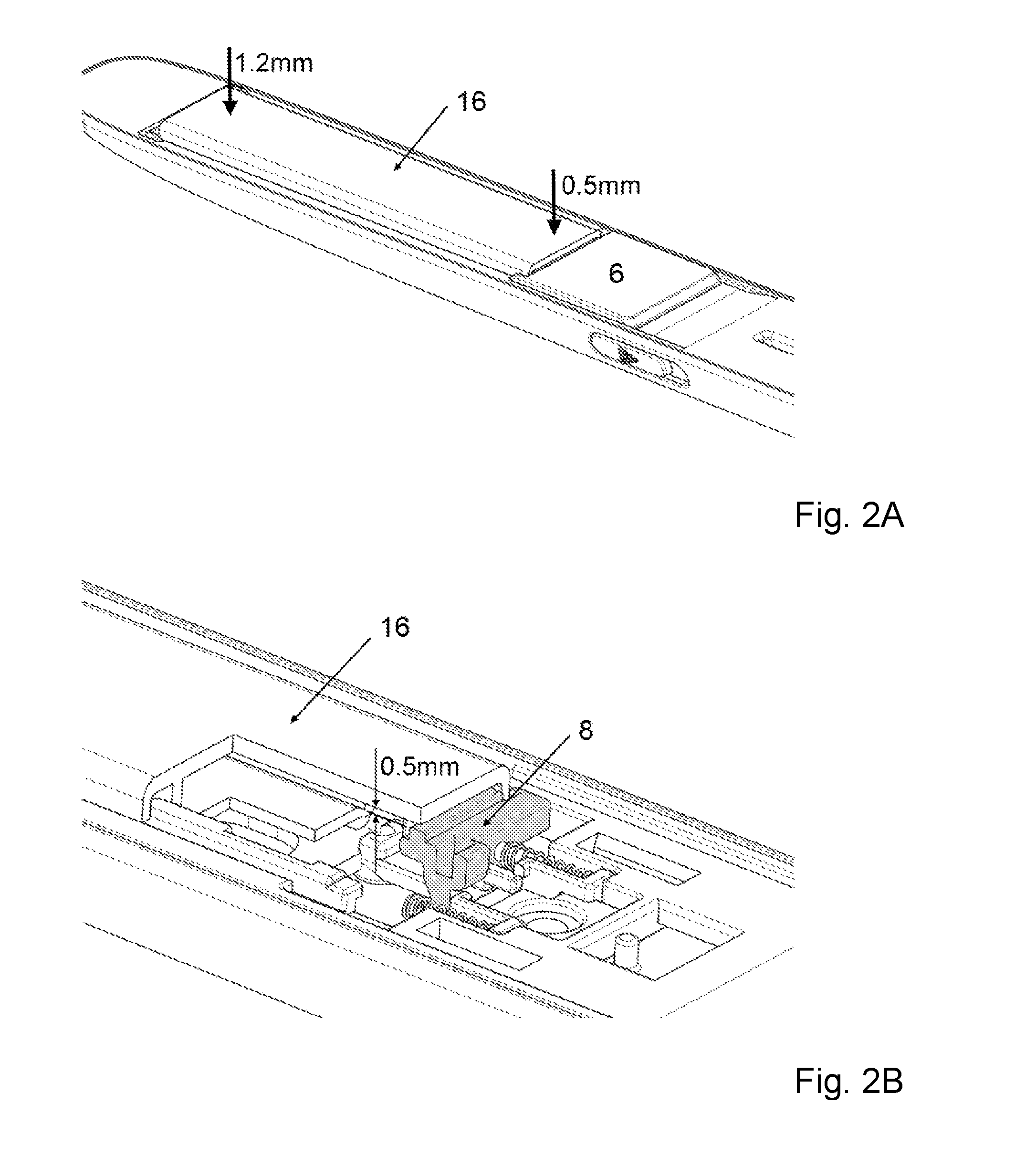
[0039]FIGS. 2...


PUM


Abstract

A hair styling device comprising two jaws, at least one jaw (1) of which having a resiliently mounted heating plate (16) that is allowed to move in such a way, that when the hair styling device is fully closed, both a first maximal gap at a proximal end of the heating plate (16) between the heating plate (16) and a mating element of the other jaw in the absence of a detachable holder (5) with a hair treatment agent, and a second maximal gap at the proximal end of the heating plate (16) between the detachable holder (5) and the mating element of the other jaw in the presence of the detachable holder (5), are within a range of about 1 mm-1.5 mm.

Description

[0001]This application is the U.S. National Phase application under 35 U.S.C. §371 of International Application No. PCT / IB2014 / 062852, filed on Jul. 4, 2014, which claims the benefit of European Application No. 13177743.5 filed on Jul. 24, 2013. These applications are hereby incorporated by reference herein.FIELD OF THE INVENTION[0002]The invention relates to a hair styling device.BACKGROUND OF THE INVENTION[0003]EP 1 030 571 discloses a hair forming appliance with a handle portion, a heating portion for heating the hair, and a clamping member adapted to be moved into an open and a closed state, with the hair being insertable between the heating portion and the clamping member, in which provision is made for a pressing member arranged between the heating portion and the clamping member for exerting a pressure on the hair, and the pressing member is resiliently mounted on the hair forming appliance. The pressing member is carried by two springs arranged in particular at opposite ends...

Claims


Application Information

Patent Timeline
Patent Type & Authority Patents(United States)
IPC IPC(8): A45D1/00A45D1/14A45D19/16A45D1/06A45D2/40A45D2/00A45D1/04
CPCA45D2/001A45D1/06A45D1/14A45D19/16A45D1/04
Inventor YU, WAI KONG
Owner KONINKLJIJKE PHILIPS NV
Why Eureka
Try Eureka