Method and optical device for super-resolution localization of a particle

a particle and super-resolution technology, applied in the field of super-resolution microscopy methods and optical devices, can solve the problems of deteriorating algorithms, unable to make rapid adjustments, and both cylindrical-lens and biplane techniques

Active Publication Date: 2016-11-29
IMAGINE OPTIC
View PDF5 Cites 2 Cited by
  • Summary
  • Abstract
  • Description
  • Claims
  • Application Information

AI Technical Summary

Benefits of technology

[0016]The use, in the three-dimensional localization method according to one or more embodiments of the invention, of a wavefront-modulating device both to correct optical defects present between the emitting particle and the detection plane, and to control the deformation introduced into the wavefront emitted by the particle, in order to determine the axial position thereof, especially allows sensitivity and precision to be increased through perfect control of the PSF, thereby allowing the available “photon budget” to be adapted to a given emitting particle. Specifically, if the “photon budget”, i.e. the number of photons emitted by the emitting particle, is large, it will be possible, while preserving a sufficient detection sensitivity, to introduce a larger-amplitude deformation of the wavefront emitted by the particle so as to widen the depth range over which the emitting particle may be observed. In contrast, with a smaller “photon budget”, the quality of the PSF will be promoted to the detriment of the depth range, in order to obtain a satisfactory detection signal, by limiting the amplitude of the deformation introduced into the wavefront emitted by the particle.
[0020]The controlled deformation is obtained using a combination of Zernike polynomials of even azimuthal order, for example an astigmatism, and more particularly a 3rd-order astigmatism. The introduction of astigmatism allows a bijective relationship to be formed between the shape of the image of the particle and the axial position of the latter by adjusting only one of the coefficients of the Zernike polynomials, when the decomposition of the wavefront is based on these polynomials. It is then possible, by adjusting the amplitude of the astigmatism introduced, to vary the axial-position range of interest of the particle.
[0021]In one or more embodiments, the method may also comprise a step of focusing dynamically on an emitting particle, said dynamic focus being obtained by controllably defocusing the wavefront emitted by said particle by way of said wavefront-modulating device. The use of the wavefront modulator in the three-dimensional localization method according to one or more embodiments of the invention thus makes it possible to access other functionalities, and will for example be employed to follow particles without mechanically moving the sample relative to the microscopy device.
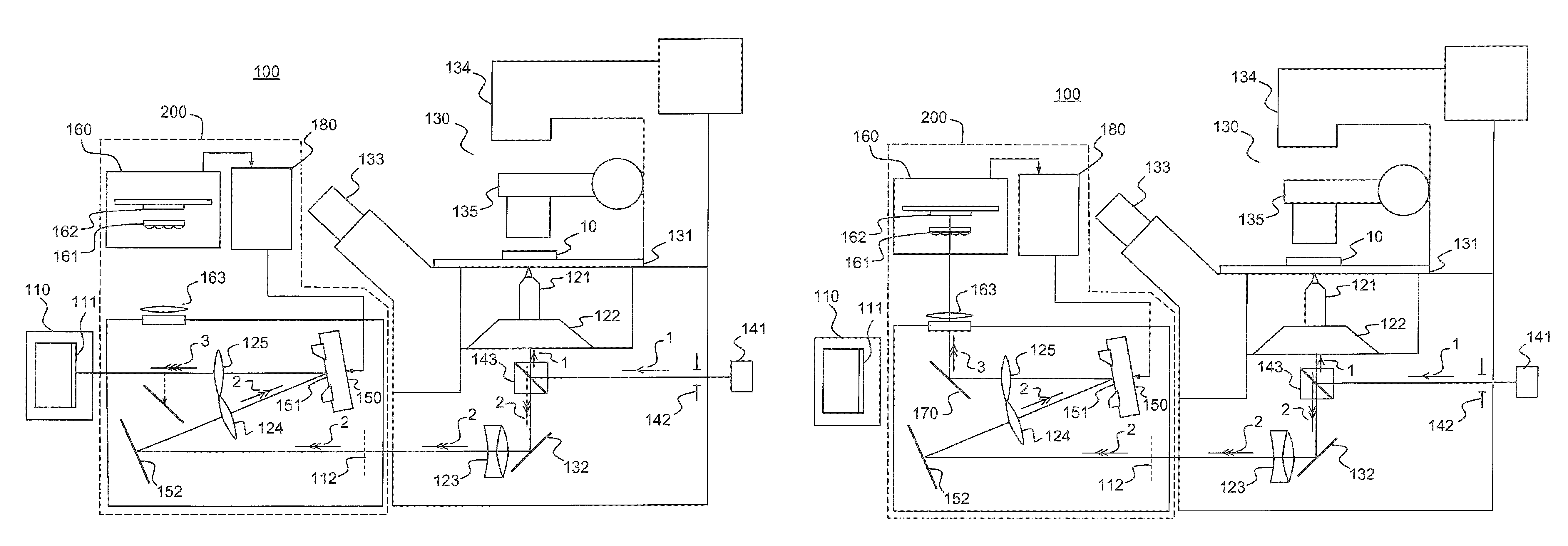
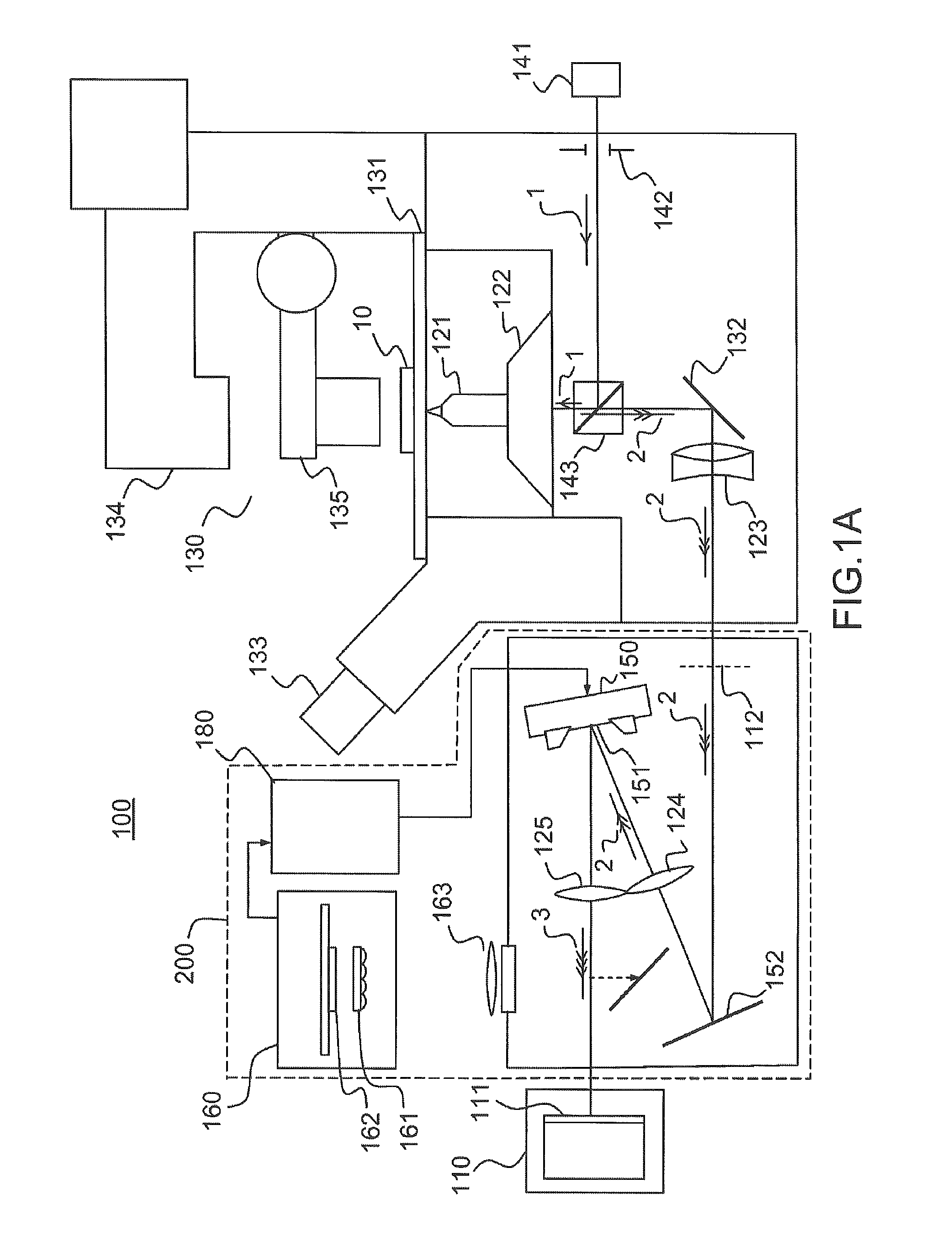
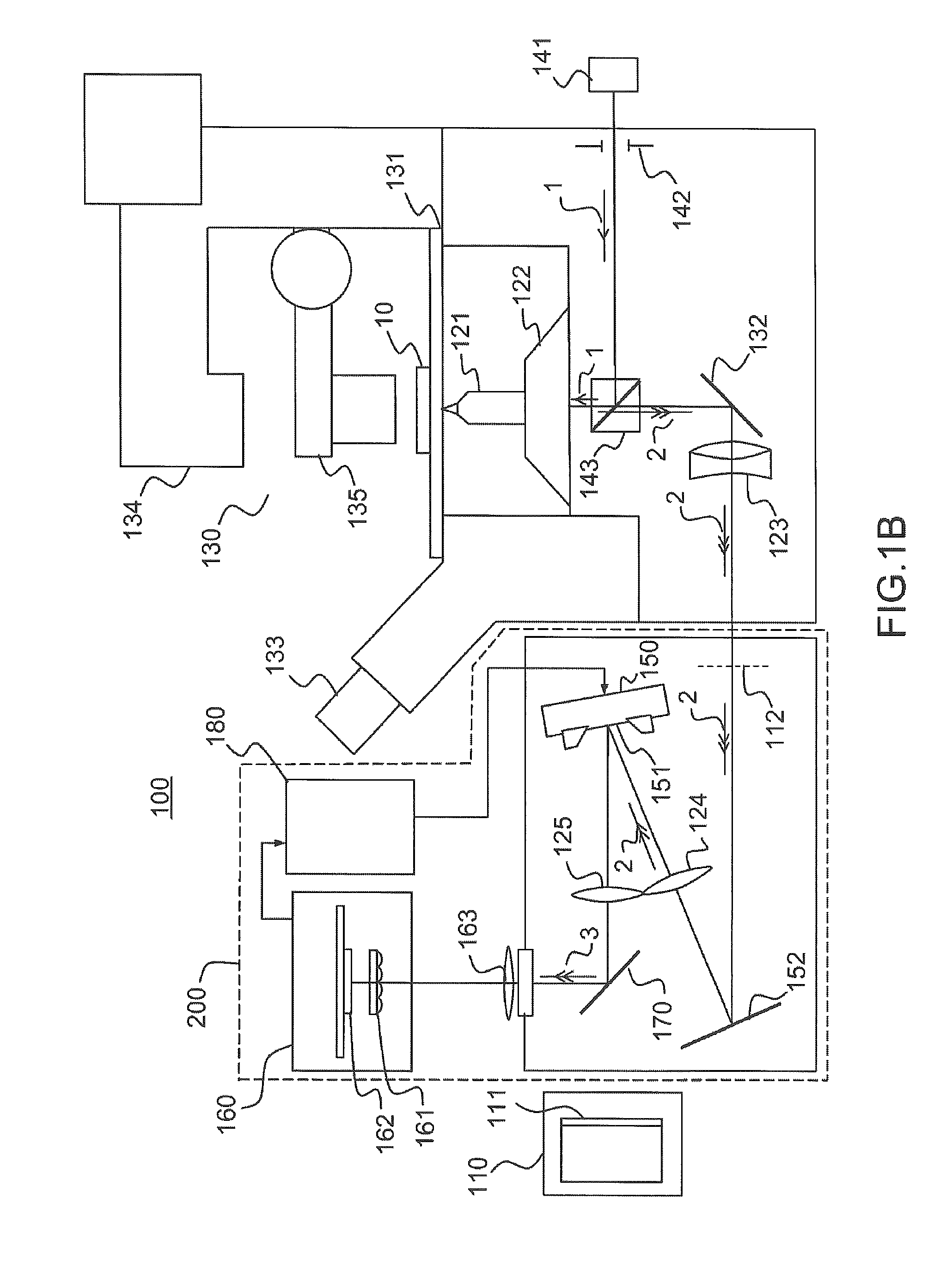
[0026]controller for controlling said device for spatially modulating wavefronts, allowing, when the wavefront-controlling device is connected to the super-resolution microscopy system, at least some of the optical defects present between said particle and said detection plane to be corrected and a controlled deformation of the wavefront to be introduced, allowing a bijective relationship between the shape of the image of said emitting particle in the detection plane and the axial position of said emitting particle relative to an object plane, which is optically conjugated with the detection plane, to be formed in a given range of values of said axial position of the particle.
[0027]Thus, it is possible to form a “module” able to be connected to any super-resolution microscopy system in order to improve the sensitivity and increase the functionalities thereof. Such a wavefront-controlling device will possibly and advantageously comprise mechanical interfaces for connection to the super-resolution microscopy system, between the microscope and the detector of said microscopy system.
[0033]controller for controlling said device for spatially modulating wavefronts, allowing at least some of the optical defects present between said particle and said detection plane to be corrected and a controlled deformation of the wavefront to be introduced, allowing a bijective relationship between the shape of the image of said emitting particle in the detection plane and the axial position of said emitting particle relative to an object plane, which is optically conjugated with the detection plane by the microscope imaging system, to be formed in a given range of values of said axial position of the particle.

Problems solved by technology

However, a limitation that is common to both the cylindrical-lens and biplane techniques is related to residual optical aberrations that deform the PSF and deteriorate the algorithms for laterally and axially localizing the emitting particle.
Moreover, the depth (range) over which it is possible to determine the axial position of the molecule is limited (to about 1-2 μm) and is entirely fixed by the opto-mechanical elements of the apparatus, meaning that it is impossible to make rapid adjustments.
This is clearly an obstacle to optimum use of the “photon budget”, this optimum use depending on the different types of fluorophore used and the biological applications in question.
Moreover, at the present time the latter technique enables the best localization in z, but at the price of considerable experimental complexity (4pi measuring system and triple interferometric detection of emitted photons) which confines it to marginal use in biological laboratories.
In addition, it remains limited to fixed samples.

Method used


Image

  • Method and optical device for super-resolution localization of a particle
  • Method and optical device for super-resolution localization of a particle
  • Method and optical device for super-resolution localization of a particle

Examples


Embodiment Construction

[0048]FIGS. 1A and 1B illustrate a device 100 for three-dimensional localization of one or more emitting particles according to one example of the invention.

[0049]The expression “emitting particle” is understood in the present description to mean any particle capable of emitting a light signal, either spontaneously or by activation, for example by way of a light source (photoactivation). The particles are, for example, reactive units or macromolecular complexes formed by proteins or assemblies of proteins, tagged, using known techniques, with a probe capable of emitting a light signal, for example a fluorescent probe. Average sizes typically range from a few nanometers for small complexes to about 100 nanometers for the largest structures. Most molecular complexes are between 10 and 30 nm in size. In any case, it is desired to localize emitting particles of smaller size than the diffraction limit of the optical system used to form an image thereof. The particles that it is desired t...


PUM


Abstract

A super-resolution microscopy method includes forming an image of an emitting particle in a detection plane of a detector by a microscopy imaging system and correcting, by a wavefront-modulating device, at least some of the optical defects present between the emitting particle and the detection plane. The method further includes introducing, via the wavefront-modulating device, a deformation of the wavefront emitted by the emitting particle, of variable amplitude, allowing a bijective relationship to be formed between the shape of the image of the emitting particle in the detection plane and the axial position of the emitting particle relative to an object plane that is optically conjugated with the detection plane by the microscopy imaging system. The method further includes controlling the amplitude of the deformation of the wavefront by controlling the wavefront-modulating device, as a function of the given range of values of the axial position of the particle.

Description

CROSS REFERENCE TO RELATED APPLICATIONS[0001]This is a national stage application based on PCT / EP2012 / 063511, filed on Jul. 10, 2012, which claims priority to French Patent Application No. 1156647, filed on Jul. 21, 2011. This application claims priority to these prior applications and incorporates their disclosures by reference in their entireties.BACKGROUND[0002]One or more embodiments of the present invention relates to a super-resolution microscopy method and optical device, i.e. with a resolution below the diffraction limit, for three-dimensional localization of one or more particles.[0003]Mankind's understanding of the dynamic architecture of cells is in the process of being completely transformed by technological developments allowing individual molecules to be detected optically in living systems. By virtue of ultrasensitive measuring methods, it is now possible to count, localize and follow the movement of biological molecules in their cellular environment (see for example ...

Claims


Application Information

Patent Timeline
Patent Type & Authority Patents(United States)
IPC IPC(8): G02B27/58G02B21/00G02B26/06G02B23/26
CPCG02B21/0004G02B26/06G02B27/58G01N21/6458
Inventor LEVECQ, XAVIERANDILLA, JORDI
Owner IMAGINE OPTIC
Why Eureka
Try Eureka