Infrared thermal wave destructive interference detecting device and method for fiber metal laminate defect using linear frequency modulation pulse coherent laser excitation

A technology of fiber metal laminates and chirps, which is applied in the field of devices for detecting defects in fiber metal laminates, can solve problems such as threats to the safety and reliability of aerospace vehicles, and achieve the effect of reducing performance requirements and increasing the depth range

Pending Publication Date: 2019-01-15
HARBIN UNIV OF COMMERCE
View PDF7 Cites 3 Cited by
  • Summary
  • Abstract
  • Description
  • Claims
  • Application Information

AI Technical Summary

Problems solved by technology

These defects and damage will have a direct impact on the quality, performance and service life of FMLs, and even pose a serious threat to the operational safety and reliability of aerospace vehicles using this material

Method used


Image

  • Infrared thermal wave destructive interference detecting device and method for fiber metal laminate defect using linear frequency modulation pulse coherent laser excitation
  • Infrared thermal wave destructive interference detecting device and method for fiber metal laminate defect using linear frequency modulation pulse coherent laser excitation

Examples


specific Embodiment approach 1

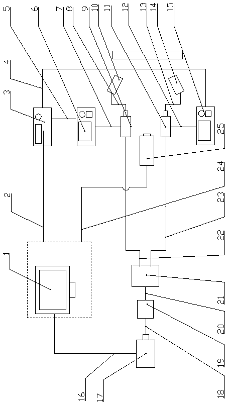
[0029] Specific implementation mode 1: This implementation mode provides a chirp coherent laser excitation infrared thermal wave destructive interference detection device for defects in fiber metal laminates, such as figure 1 As shown, the shown device consists of a computer 1, a first signal line 2, a dual-channel function generator 3, a second signal line 4, a third signal line 5, a first RF drive source 6, a fourth signal line 7, a tenth A signal line 8, a first acousto-optic modulator 9, a first beam expander shaping mirror 10, a second acousto-optic modulator 11, a fifth signal line 12, a twelfth signal line 13, a second beam expander shaping mirror 14, The second RF driving source 15, the sixth signal line 16, the laser 17, the seventh signal line 18, the amplifier 19, the eighth signal line 20, the fiber beam splitter 21, the ninth signal line 22, the tenth signal line 23, the tenth signal line Three signal lines 24 and an infrared thermal imager 25 are formed, wherein:...

specific Embodiment approach 2

[0043] Embodiment 2: This embodiment provides a method for detecting fiber metal laminate defect chirp coherent laser excitation infrared thermal wave destructive interference detection using the device described in Embodiment 1. The steps of the method are as follows:

[0044] Step 1: complete and check the communication connection of each component and element of the device as required;

[0045] The second step: adjust the thermal imaging camera 25 so that the lens of the thermal imaging camera is vertical and facing the part to be tested, and the distance is 30cm;

[0046] The third step: turn on the computer 1, the second beam expander shaping mirror 14, the dual-channel function generator 3, the first acousto-optic modulator 9, the second acousto-optic modulator 11, the infrared thermal imager 25, the amplifier 19, the first The RF drive source 6, the second RF drive source 15, the first beam expander shaping mirror 10, the fiber beam splitter 21, and the laser 17 is not ...


PUM


Abstract

The invention discloses an infrared thermal wave destructive interference detecting device and method for a fiber metal laminate defect using linear frequency modulation pulse coherent laser excitation. The device comprises a modulator, a second beam expander, an infrared camera. A computer is connected to a dual channel function generator. The dual channel function generator is respectively connected to a first RF driving source and a second RF driving source. The first RF driving source is connected to a first acousto-optic modulator. The first acousto-optic modulator is connected to a firstbeam expander. The second RF driving source is connected to a second acousto-optic modulator. The second acousto-optic modulator is connected to the second beam expander. The computer is connected toa laser. The laser is connected to an amplifier. The amplifier is connected to a fiber optic beam splitter. The fiber optic beam splitter is respectively connected to the first acousto-optic modulator and the second acousto-optic modulator. The computer is connected to the infrared camera. The infrared thermal wave destructive interference detecting device and method can significantly improve thesignal to noise ratio of the infrared thermal wave characteristic image. Moreover, the detection capability of the infrared thermal wave detecting technology is improved.

Description

technical field [0001] The invention relates to a device and method for detecting defects in fiber metal laminates, in particular to a device and method for detecting defects in fiber metal laminates with chirped pulse coherent laser excitation infrared thermal wave destructive interference. Background technique [0002] Fiber metal laminates (Fiber Metal Laminates, FMLs) are a kind of metal layer (aluminum alloy, aluminum-lithium alloy, titanium alloy, etc.) and fiber composite material layers (glass fiber, carbon fiber, graphite fiber, etc.) Interlayer hybrid composites cured under temperature and pressure. FMLs has the advantages of excellent fatigue damage tolerance performance, impact resistance, corrosion resistance, high flame retardancy and easy processing and molding. It is a popular advanced composite material in the aerospace industry, especially in aircraft skins and wing leading edges. It is widely used in key structures that have high requirements on impact an...

Claims


Application Information

Patent Timeline
Patent Type & Authority Applications(China)
IPC IPC(8): G01N25/72
CPCG01N25/72
Inventor 卜迟武唐庆菊张喜斌陈江于兴滨
Owner HARBIN UNIV OF COMMERCE
Why Eureka
Try Eureka