Optical imaging method and optical imaging apparatus

a technology of optical imaging which is applied in the field of optical imaging methods and optical imaging apparatus, can solve the problems of reducing the application range of optical imaging techniques, limiting the demand for obtaining the broadest possible image range, and complex conjugate ambiguity of reconstructed a-line profiles, so as to achieve the effect of extending the imaging depth range and reducing costs

Active Publication Date: 2013-01-31
KK TOPCON
View PDF4 Cites 5 Cited by
  • Summary
  • Abstract
  • Description
  • Claims
  • Application Information

AI Technical Summary

Benefits of technology

[0053]According to the present invention, by forming a tomographic image based on the plurality of detection results sequentially obtained by performing scanning while alternately changing the phase difference between the signal light and the reference light to two phase differences, it is possible to extend the imaging depth range at a lower cost.

Problems solved by technology

However, because the spectral interferogram is detected in real values, the reconstructed A-line profile suffers from complex conjugate ambiguity.
Consequently, the demand to obtain the broadest possible image range is restricted.
However, the implementation of these techniques is limited by certain practical issues as described below.
These techniques are limited by devices such as a piezo stage or electrical phase modulator.
Moreover, these techniques are compromised by factors such as mechanical instability of a system and chromatic errors.
The former has some of the drawbacks of phase shifting and is not cost-effective in achieving a stepwise phase change.
The latter causes an undesirable situation in which the path length is changed when the range of transverse scanning is widened.
Moreover, frequency shifting requires expensive devices such as EOM (electro-optic modulators) and AOM (acousto-optic modulators) in order to shift the signal to a higher frequency band.
As a result, this system also requires significantly high speed data acquisition devices.
3×3 fiber-optical coupler-based techniques suffer from wavelength-dependent coupling coefficients for broadband and require additional costly detectors.
This causes several major problems.
In other words, when demodulating the modulation signal in phase modulation, at least 3 signals have to be detected, so there is a problem in terms of hardware or software as well as a problem in that a higher measurement band is required in order to detect higher order modulation signals without aliasing.

Method used


Image

  • Optical imaging method and optical imaging apparatus
  • Optical imaging method and optical imaging apparatus
  • Optical imaging method and optical imaging apparatus

Examples


implementation example

[0097]An example of implementing this embodiment will be described below.

[Configuration]

[0098]A configuration example of the optical imaging apparatus according to this embodiment is shown in FIG. 6. Although an apparatus using SS-OCT will be described herein, a similar configuration can also be applied to an apparatus using SD-OCT. That is, the difference between the apparatus using SS-OCT according the invention and the apparatus using SD-OCT according to the invention is merely the general difference between SS-OCT and SD-OCT.

[Overall Configuration]

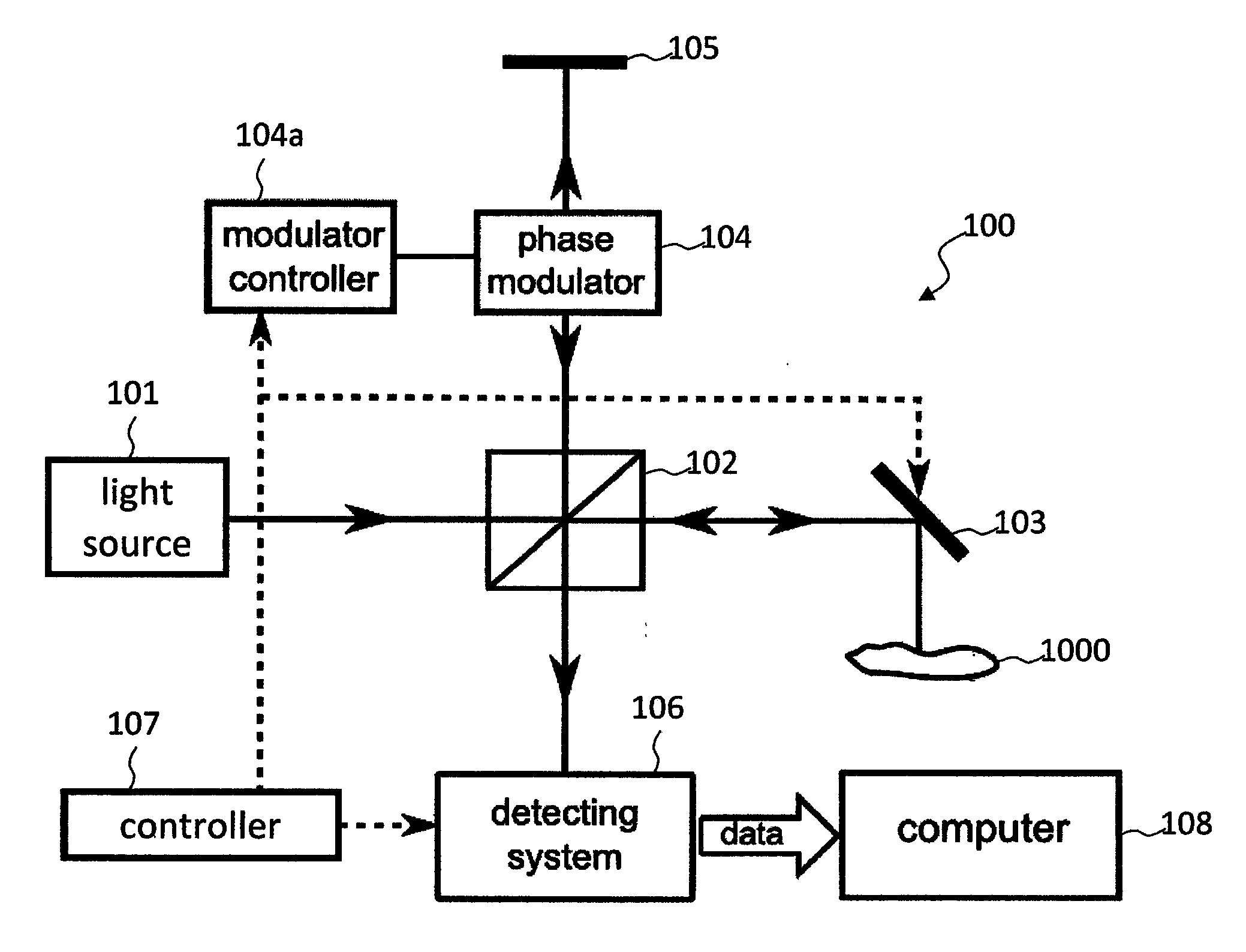
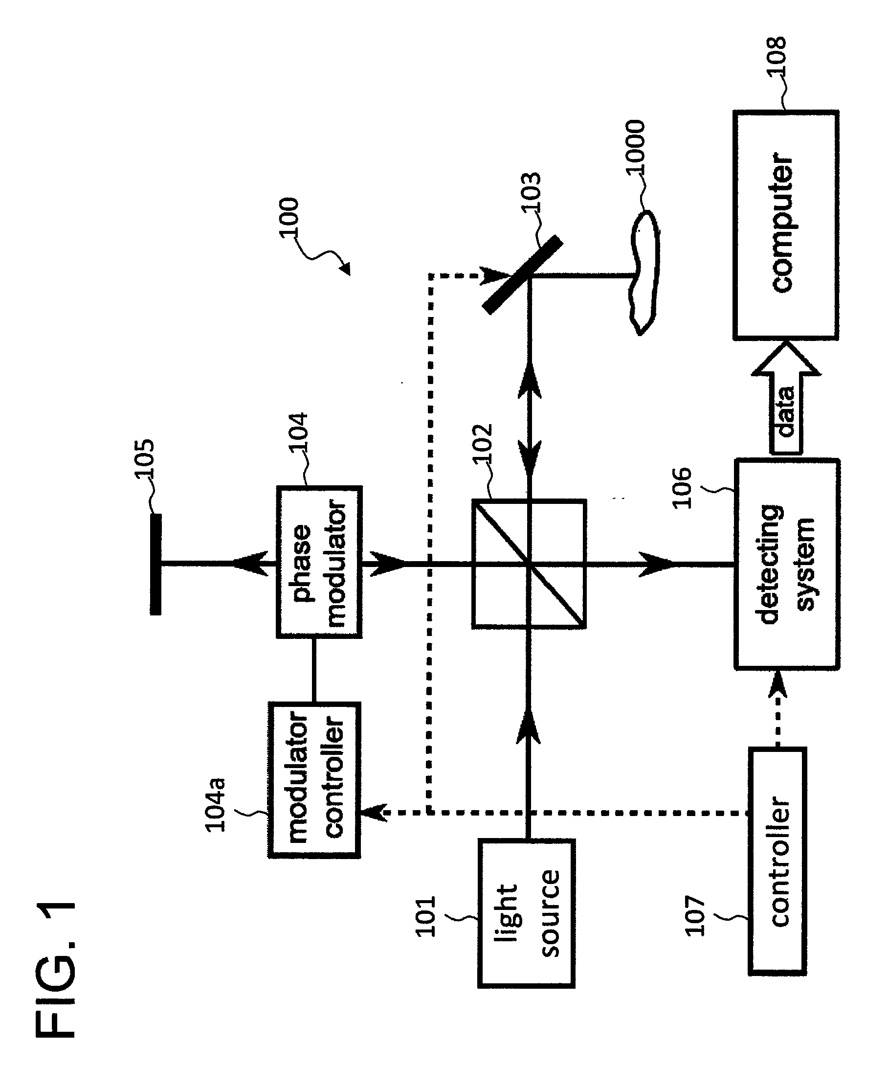
[0099]An optical imaging apparatus 400 shown in FIG. 6 has a wavelength-swept light source 401 such as a wavelength-variable laser. The wavelength-swept light source 401 outputs a light while continuously changing the wavelength at a high speed. The light output from the wavelength-swept light source 401 travels through an optical fiber 402 and is directed to a fiber coupler 403. The fiber coupler 403 connects four optical fibers 402, ...

examples

[0119]The inventors performed measurement of a human eye using such a phase alternating SS-OCT. The oversampling ratio was set to Rs=8. Here, the oversampling ratio Rs is determined as a ratio of the focus spot size w and the step size (distance between adjacent A-lines) Δx of the transverse scanning as follows: Rs=w / Δx.

[0120]The A-line profile obtained by this example is shown in FIG. 10A. Moreover, the A-line profile obtained by the conventional method is shown in FIG. 10B. It should be noted that the lateral axis of each A-line profile indicates the depth z, and the longitudinal axis indicates the intensity I of the backscattered light.

[0121]The A-line profile AP2 according to the conventional method includes a true image Q1 as well as its complex conjugate, a mirror image Q2. On the other hand, the A-line profile AP1 according to the present example does not have a mirror image, and includes only a true image P1.

[Operation]

[0122]The operation of the present embodiment will be de...


PUM


Abstract

An optical imaging method is provided that can realize, at low cost, the extension of the imaging depth range. An optical imaging apparatus 400 is an apparatus that forms a tomographic image of an object using FD-OCT, and performs a scanning step, detection step and imaging step. In the scanning step, the object is scanned with a signal light while alternately changing the phase difference between the signal light and a reference light to two preset phase differences. In the detection step, interference light of the signal light passing through the object and the reference light is detected. In the imaging step, a tomographic image of the object is formed based on the detection results of a plurality of the interference lights sequentially obtained in the detection step according to the scanning.

Description

FIELD OF THE INVENTION[0001]The present invention relates to an optical imaging method and an optical imaging apparatus using optical coherence tomography.BACKGROUND OF THE INVENTION[0002]Optical coherence tomography (abbreviated OCT) is a technique for forming a tomographic image of an object by detecting the interference light of a signal light passing through the object and a reference light. The OCT is used in, for example, the medical field due to the advantage of high resolution images being obtained quickly and non-invasively.[0003]The major advance in this technique is Fourier domain OCT (abbreviated FD-OCT). With FD-OCT, a measurement speed several dozen to several hundred times faster compared to conventional time domain OCT (abbreviated TD-OCT) can be achieved.[0004]FD-OCT includes spectral domain OCT (abbreviated SD-OCT) in which the interference light is detected through spectral decomposition and swept source OCT (abbreviated SS-OCT) in which interference lights of var...

Claims


Application Information

Patent Timeline
Patent Type & Authority Applications(United States)
IPC IPC(8): G01B9/02
CPCA61B3/102G01B9/02004G01B9/02078G01B9/02091G01B9/02069G01B9/0201
Inventor YUAN, ZHIJIAWANG, ZHENGUOCHAN, KINPUI
Owner KK TOPCON
Why Eureka
Try Eureka