Image fusing method

a thermal image and fusion technology, applied in the field of fusion, can solve the problem of reducing the definition of an image, and achieve the effect of improving the overall definition of an imag

Active Publication Date: 2016-11-29
HANWHA VISION CO LTD
View PDF8 Cites 4 Cited by
  • Summary
  • Abstract
  • Description
  • Claims
  • Application Information

AI Technical Summary

Benefits of technology

[0012]Exemplary embodiments of the inventive concept include methods of fusing a thermal image and a visible image, which may improve the overall definition of an image in a relatively bright region.

Problems solved by technology

However, the definition of an image is reduced in a certain portion of the relatively bright region due to high luminance of the thermal image.

Method used


Image

  • Image fusing method
  • Image fusing method
  • Image fusing method

Examples


Embodiment Construction

[0046]Reference will now be made in detail to exemplary embodiments, which are illustrated in the accompanying drawings, wherein like reference numerals refer to like elements throughout. In this regard, the exemplary embodiments may have different forms and should not be construed as being limited to the descriptions set forth herein. Accordingly, the exemplary embodiments are merely described below, by referring to the figures, to explain aspects of the inventive concept.

[0047]The following descriptions and the accompanying drawings are for understanding operations according to the exemplary embodiments, and descriptions of well-known features, which may be easily implemented by those of ordinary skill in the art, will be omitted for conciseness.

[0048]Also, the specification and the drawings are not intended to limit the scope of the inventive concept, and the scope of the inventive concept is to be defined by the appended claims. For the best understanding of the inventive concep...


PUM


Abstract

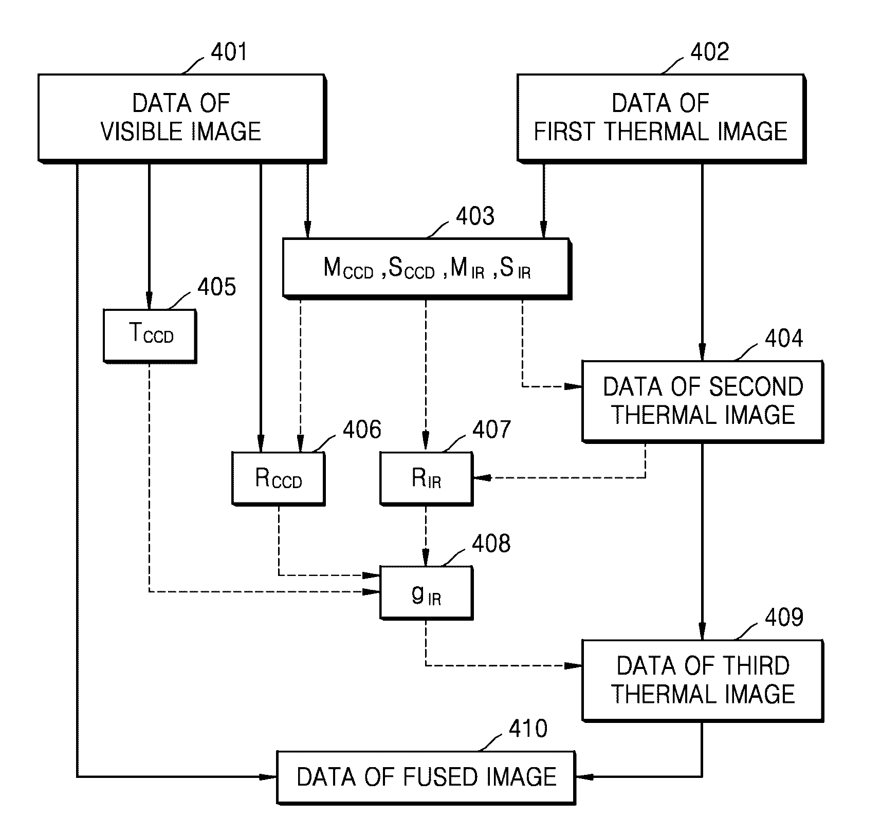
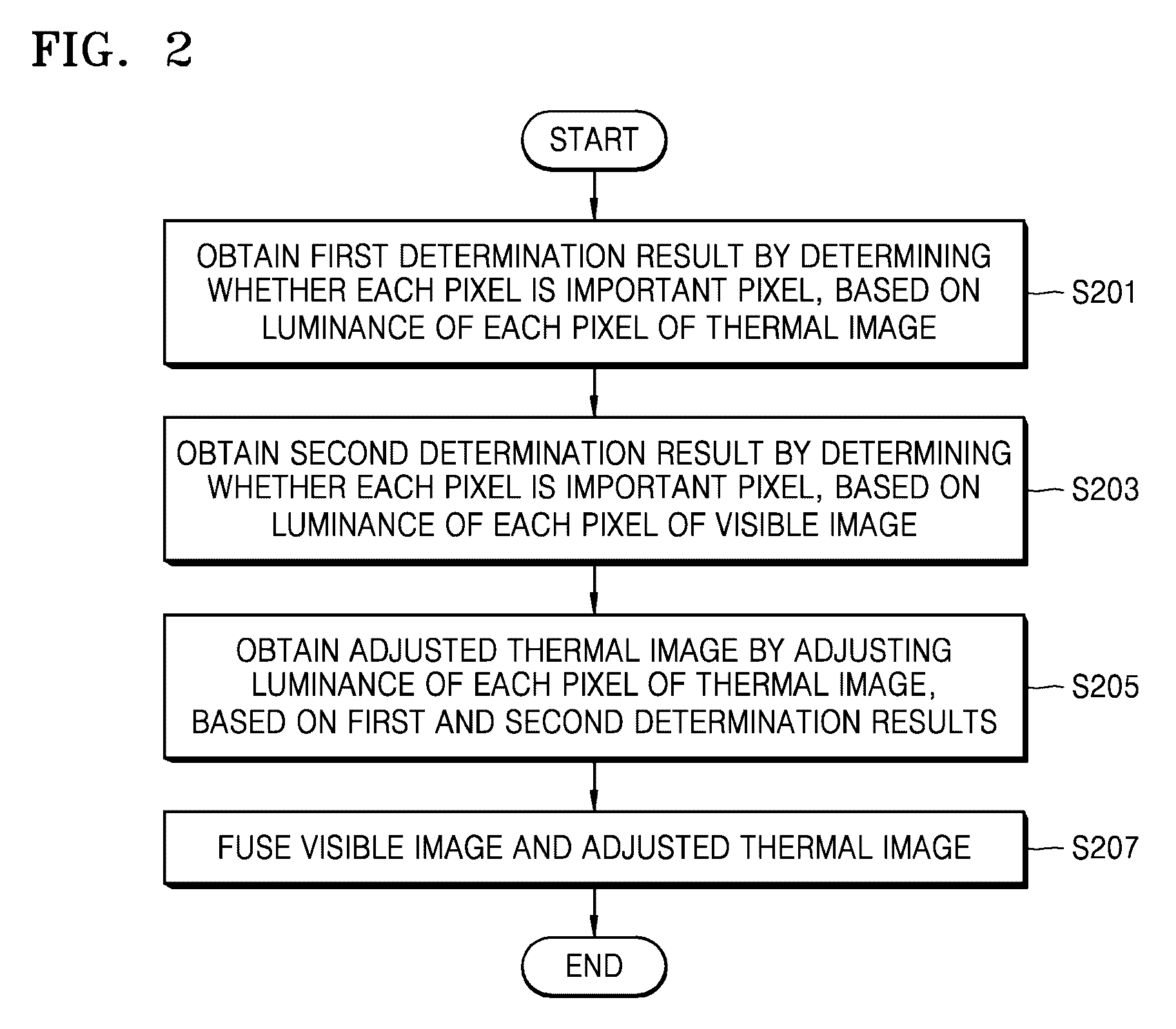
Provided is an image fusing apparatus for fusing a thermal image and a visible image of a subject. The image fusing apparatus includes: a determination processor configured to determine importance of each pixel, based on a luminance value thereof, of the thermal image and the visible image; a pixel coefficient setting processor configured to set a pixel coefficient for each pixel of the thermal image based on the importance of each pixel of the thermal image and the visible image; a thermal image processor configured to generate another thermal image by applying the pixel coefficient to the luminance value of each pixel of the thermal image; and an image fusing processor configured to fuse the other thermal image and the visible image to generate a fused image.

Description

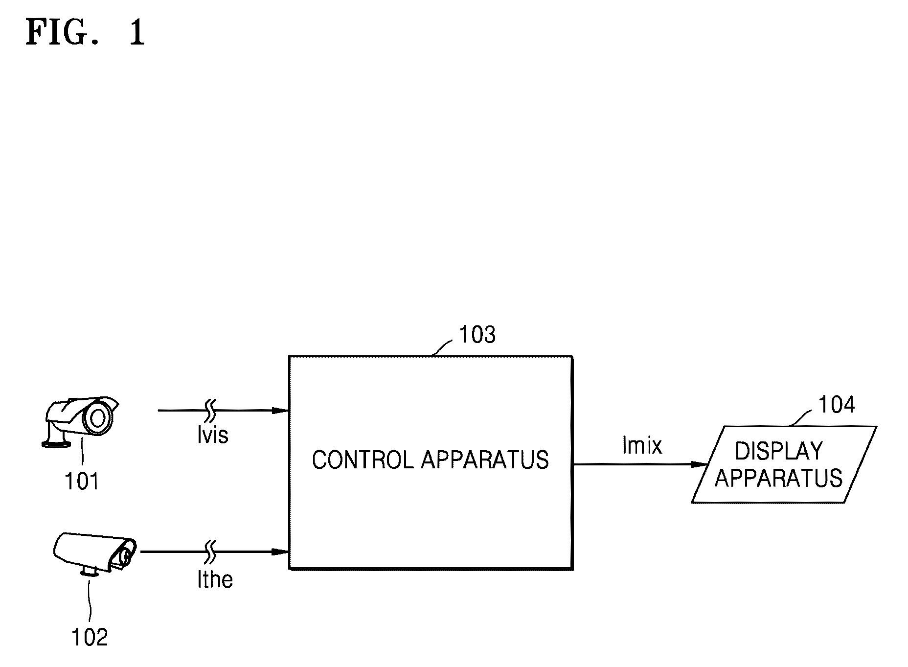
CROSS-REFERENCE TO THE RELATED APPLICATION[0001]This application claims priority from Korean Patent Application No. 10-2014-0054928, filed on May 8, 2014, in the Korean Intellectual Property Office, the disclosure of which is incorporated herein in its entirety by reference.BACKGROUND[0002]1. Field[0003]Apparatuses and methods consistent with exemplary embodiments relate to image fusing, and more particularly, to fusing a thermal image of a subject and a visible image of the subject.[0004]2. Description of the Related Art[0005]In a monitoring system including a visible image camera, a control apparatus and a display apparatus, a monitor observing a moving image in the display apparatus has relatively low information recognition ability and situation management ability in a night illumination range.[0006]Accordingly, a thermal image camera capturing a thermal image of a subject has recently been added to display a fused image resulting from fusing a thermal image and a visible image....

Claims


Application Information

Patent Timeline
Patent Type & Authority Patents(United States)
IPC IPC(8): G06K9/40G06T11/60G06T5/00G06T5/50H04N5/33
CPCG06T5/50G06T5/009G06T11/60G06T2207/10024G06T2207/10048G06T2207/20221G06T2207/30232H04N5/332H04N23/11
Inventor LEE, JOONSUNGBAE, JEONGMIN
Owner HANWHA VISION CO LTD
Why Eureka
Try Eureka