Image brightness controlling apparatus and method thereof

a brightness control and brightness technology, applied in image enhancement, instruments, computing, etc., can solve the problems of image quality not improving, image appearance very unnatural, noise rather increasing, etc., and achieve the effect of enhancing the degree of stretching

Active Publication Date: 2011-08-25
MTEKVISION CO LTD
View PDF9 Cites 33 Cited by
  • Summary
  • Abstract
  • Description
  • Claims
  • Application Information

AI Technical Summary

Benefits of technology

[0057]The weight may be set to enhance the degree of stretching as the dynamic range based on the dynamic range information is wider. The weight may be independently controlled on the basis of an asymmetry parameter input from the user.

Problems solved by technology

However, when the range of pixel values of the input image is very narrow but the dynamic range is forcibly enhanced into the values between 0 and 2n-1, the quality of image is not improved, but noises rather increases and the image is made to seem very unnatural.
Since the image brightness controlling method using Expression 2 is performed in a frequency domain, there is a problem with troublesome calculation such as Fourier transformation should be performed.
Since the calculation could not be performed in real time, there is also a problem in that the method could be performed only as a post process.

Method used


Image

  • Image brightness controlling apparatus and method thereof
  • Image brightness controlling apparatus and method thereof
  • Image brightness controlling apparatus and method thereof

Examples


first embodiment

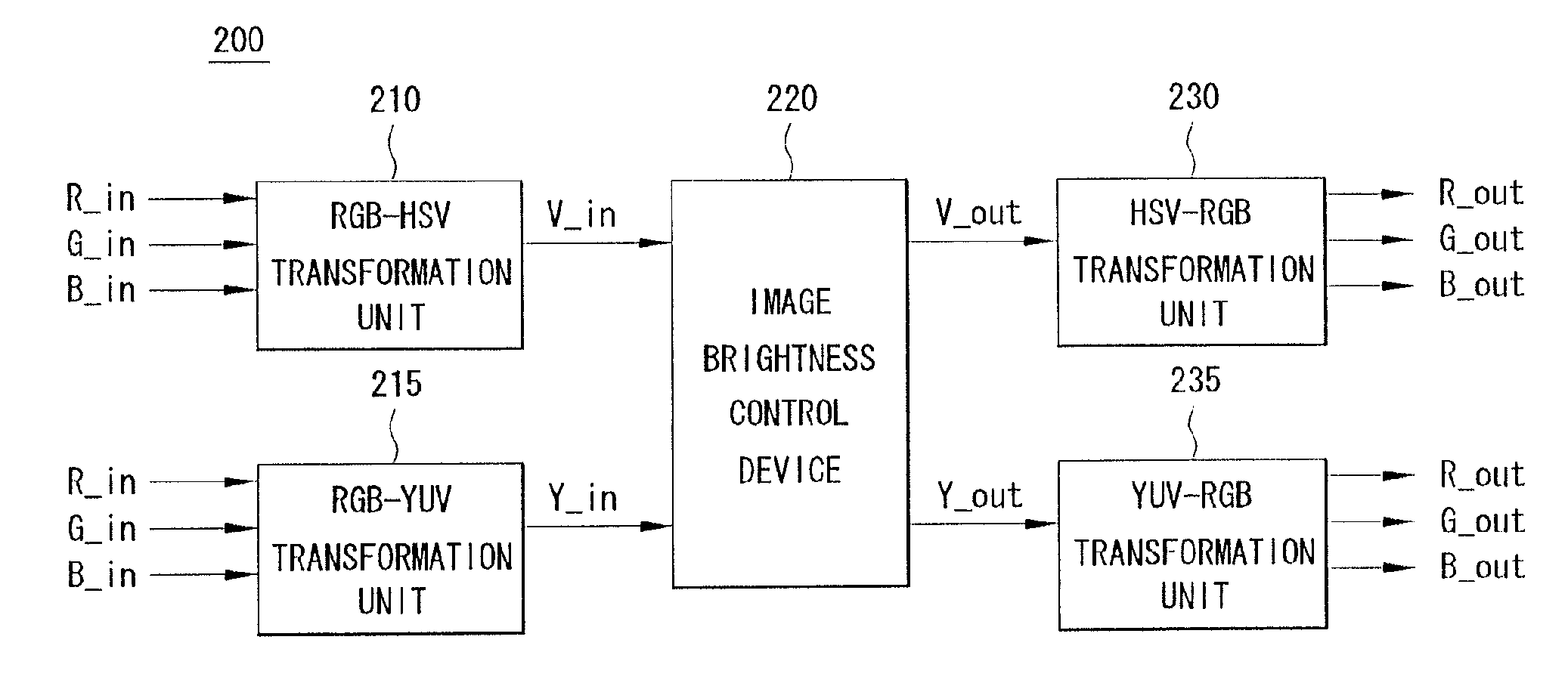
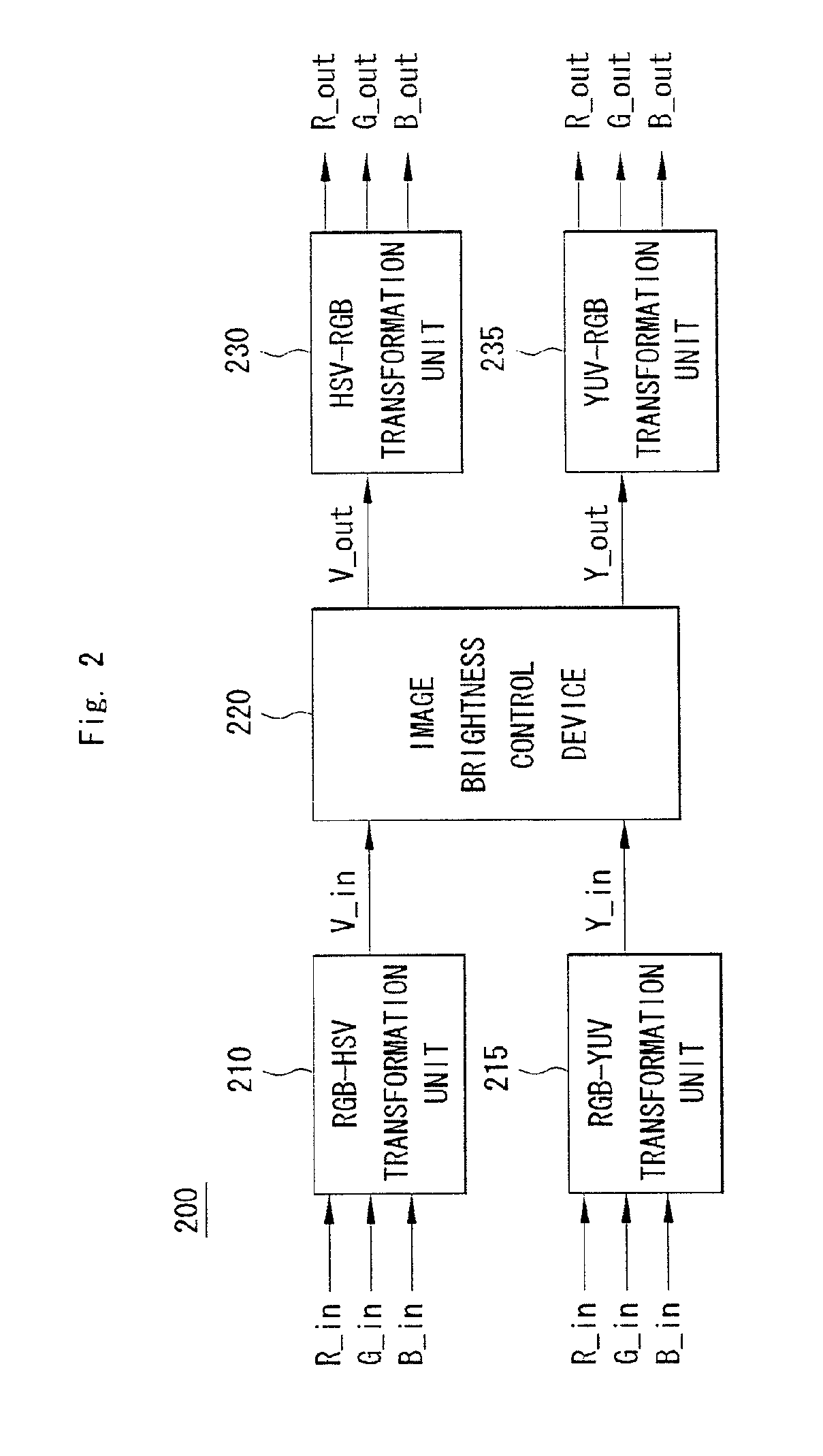
[0112]The image brightness control device 220 controls the image brightness using the brightness value of the input image. an image brightness control device 220 can improve the definition of brightness of the whole image.

[0113]According to a second embodiment, an image brightness control device 220 can improve the definition of brightness of local areas of the image using the local brightness information. According to a third embodiment, an image brightness control device 220 can primarily improve the definition of brightness of the whole image and secondarily improve the definition of brightness of the local areas using the local brightness information.

[0114]Now, the image brightness control device 220 and a method for improving the definition of brightness of the whole image according to the first embodiment will be described.

[0115]FIG. 3 is a diagram schematically illustrating a configuration of the image brightness control device according to the first embodiment of the invent...

second embodiment

[0152]FIG. 6 is a diagram schematically illustrating an image brightness control device according to the invention and FIG. 7 is a diagram schematically illustrating a dynamic range information acquiring unit. FIG. 8 is a diagram illustrating a method of calculating a local brightness average, FIG. 9 is a diagram illustrating a graph of a bias curve, FIG. 10 is a diagram illustrating a bi-linear interpolation method, and FIG. 11 is a diagram illustrating a graph of a weighting function.

[0153]The image brightness control device 220 according to the second embodiment of the invention includes a preprocessing unit 610 and a tone mapping unit 620 (see FIG. 6). The preprocessing unit 610 acquires dynamic range information and local brightness averages from the input image. The tone mapping unit 620 tone-maps the input image using the acquired dynamic range information and the acquired local brightness averages.

[0154]Here, the preprocessing unit 610 acquires the dynamic range information ...

third embodiment

[0191]According to the invention, the image brightness control device 220 can primarily improve the definition of brightness of the entire image or secondarily improve the definition of brightness of the local areas using the local brightness information.

[0192]Since the primary improvement in definition of brightness of the entire image has been described with reference to FIGS. 3 to 5, and the secondary improvement in definition of brightness of the local areas using the local brightness information has been described with reference to FIGS. 6 to 12, detailed description thereof is omitted.

[0193]FIG. 13 shows an original image and FIG. 14 is a diagram illustrating an output image acquired by applying the image brightness control method according to the first embodiment of the invention to the original image shown in FIG. 13. FIG. 15 shows an original image and FIG. 16 is a diagram illustrating an output image acquired by applying the image brightness control method according to the...


PUM


Abstract

Provided are an image brightness control device and an image brightness control method for improving the definition of brightness of the entire image and/or improving the definition of brightness of local areas using local brightness information. The image brightness controlling device includes: a preprocessing unit acquiring an offset table for controlling a dynamic range corresponding to an image range of an input image using brightness values of color data of the input image; and a tone mapping unit mapping the offset table onto the color data. It is possible to improve the definition of brightness so as to correspond to the characteristic of the input image, by automatically considering how to reflect a distribution characteristic of an image.

Description

CROSS-REFERENCE TO RELATED APPLICATIONS[0001]This application claims foreign priority benefits under 35 U.S.C. .sctn. 119(a)-(d) to PCT / KR08 / 002524, filed May 6, 2008, which is hereby incorporated by reference in its entirety.BACKGROUND[0002]1. Technical Field[0003]The present invention relates to an image brightness controlling device, and more particularly, to an image brightness controlling device and a method thereof, which improves the definition of brightness by the use of the definition of brightness of an entire image and / or locally improves the definition of brightness by the use of local brightness information.[0004]2. Description of the Related Art[0005]Conventional methods of controlling a dynamic range of an input image are described as follows. In the following description, it is assumed that the input image has an n-bit resolution (where n is a natural number).[0006](1) Contrast Enhancement[0007]A dynamic range is controlled between 0 and 2n-1 by applying the minimum ...

Claims


Application Information

Patent Timeline
Patent Type & Authority Applications(United States)
IPC IPC(8): G06K9/40G06K9/00
CPCG06T5/40G06T5/009
Inventor LEE, HO-YOUNG
Owner MTEKVISION CO LTD
Why Eureka
Try Eureka