
Connector with rubber plug having insertion hole to receive part of mating housing that deforms plug toward wire

a technology of rubber plugs and connectors, applied in the direction of couplings/cases, coupling device connections, securing/insulating coupling contact members, etc., can solve problems such as damage to rubber plugs, and achieve the effects of avoiding enlargement, satisfying waterproofness, and simplifying the overall structur

Active Publication Date: 2016-12-06
SUMITOMO WIRING SYST LTD
View PDF28 Cites 2 Cited by
  • Summary
  • Abstract
  • Description
  • Claims
  • Application Information

AI Technical Summary

Benefits of technology

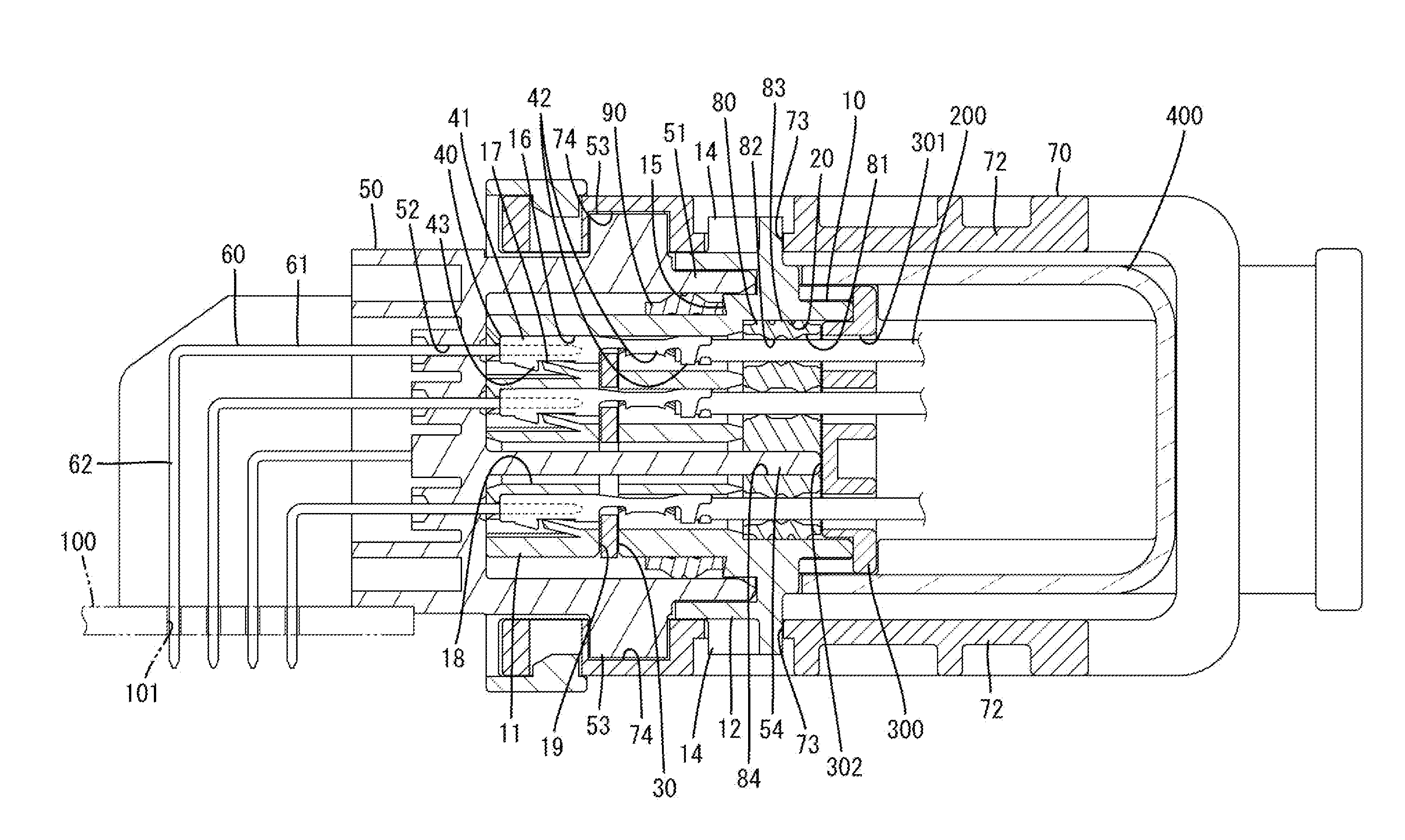
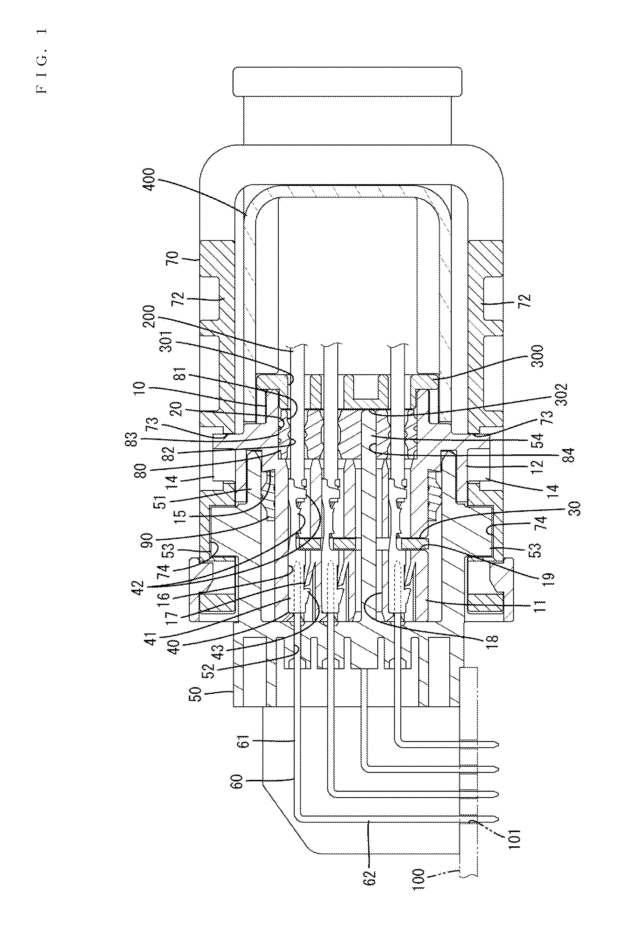
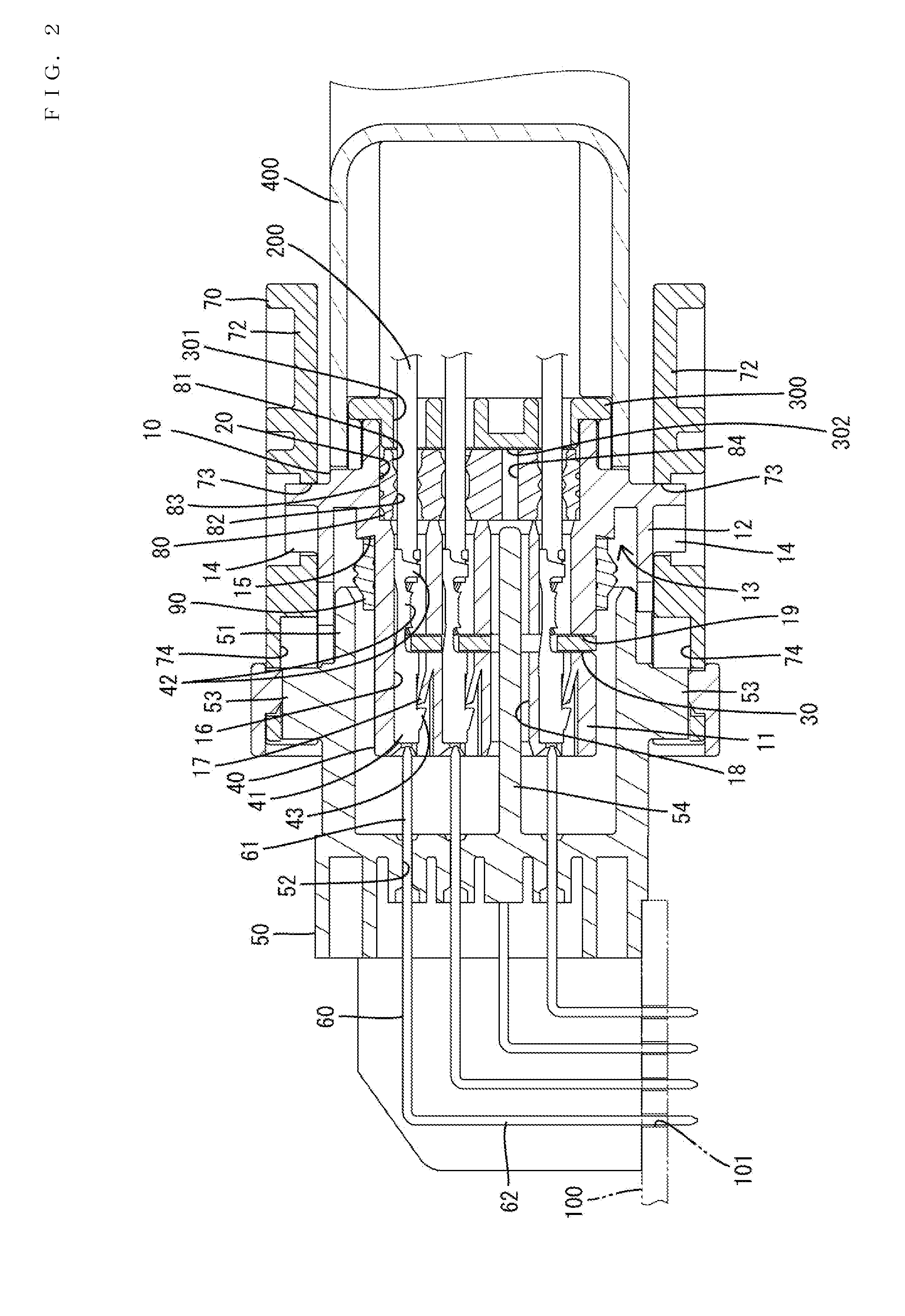
[0008]In a state before the first housing is connected to the second housing, the tip part of the wrench preventing portion is not inserted in the insertion hole of the rubber plug and no compression force is applied to the sealing holes. Thus, sliding resistance between the terminal fittings passing through the sealing holes and the rubber plug can be reduced by setting a relatively large diameter for the sealing holes. Therefore, a situation of damaging the rubber plug can be avoided.
[0009]On the other hand, when the first housing is connected to the second housing, the tip part of the wrench preventing portion is inserted into the insertion hole of the rubber plug to expand the insertion hole. Since the compression force is applied to the sealing holes, the rubber plug and the wires are in closer contact and waterproofness can be satisfactorily ensured.
[0010]Particularly, since the wrench preventing portion also has an additional function of ensuring waterproofness by expanding the insertion hole, it is not necessary to separately provide a structure for ensuring waterproofness, the overall structure can be simplified and enlargement can be avoided.
[0011]The connector is further provided with a rear holder to be mounted into the first housing and capable of holding the rubber plug while sandwiching the rubber plug between the first housing and the rear holder in a front-back direction, and the tip of the wrench preventing portion is covered with a wall surface of the rear holder at the time of the connection. Thus, the waterproofness of the rubber plug can be ensured even though the insertion hole penetrates through the rubber plug.
[0012]A plurality of the sealing holes are arranged to surround the insertion hole in the rubber plug. By such an arrangement, the compression force is substantially equally transmitted to the plurality of sealing holes and waterproofness around the wire inserted in each sealing hole can be stably maintained when the insertion hole is expanded by the wrench preventing portion.

Problems solved by technology

There is a possibility that an edge part of the terminal fitting contacts and damages the rubber plug when the terminal fitting passes through the wire insertion hole of the rubber plug.

Method used


Image

  • Connector with rubber plug having insertion hole to receive part of mating housing that deforms plug toward wire
  • Connector with rubber plug having insertion hole to receive part of mating housing that deforms plug toward wire
  • Connector with rubber plug having insertion hole to receive part of mating housing that deforms plug toward wire

Examples


Embodiment Construction

[0019]Preferred embodiments of the present invention are described below.

[0020]Hereinafter, an embodiment is described with reference to the drawings. As shown in FIGS. 1 and 2, a connector of this embodiment includes a first housing 10 and a second housing 50 connectable to each other, and an integration-type rubber plug 80 to be mounted in the first housing 10. Note that, in the following description, a surface side on which the first and second housings 10, 50 are facing each other at the time of starting a connection is referred to as a front side and a vertical direction is based on each figure. Further, a width direction is a lateral direction in FIGS. 3, 5 and 6.

[0021]The second housing 50 is made of synthetic resin and includes, as shown in FIGS. 4 and 5, a tubular receptacle 51 projecting forward. Preferably, a pair of tubular receptacles 51 are provided and are connected side-by-side. However, only a single tubular receptacle 51 is shown for the sake of convenience. As sho...


PUM


Abstract

A connector is provided with a first housing including a plurality of cavities and a passage hole, a rubber plug having a plurality of sealing holes through which wires are insertable in a liquid tight manner is mounted in the first housing. A second housing is connected to the first housing and includes a wrench preventing portion configured to regulate the connection of the second housing in an inclined posture to the first housing by being inserted into the passage hole at the time of the connection. The rubber plug includes an insertion hole which is expanded by the insertion of a tip part of the wrench preventing portion inserted through the passage hole at the time of the connection and applies a compression force to the sealing holes in a direction to be in closer contact with the wires when being expanded.

Description

BACKGROUND[0001]1. Field of the Invention[0002]The present invention relates to a connector.[0003]2. Description of the Related Art[0004]A connector disclosed in U.S. Patent Application Publication No. US 2014 / 0051276 is provided with a first housing including first cavities into which terminal fittings connected to end parts of wires are insertable, and a rubber plug to be mounted in the first housing including a plurality of wire insertion holes, at positions communicating with the cavities, into which the wires are insertable in a liquid-tight manner after the passage of the terminal fittings. A second housing is connectable to the first housing. The first housing is composed of an inner housing including the cavities and an outer housing, and the rubber plug is accommodated in a state sandwiched between a rear surface of the inner housing and a front surface of the outer housing.[0005]There is a possibility that an edge part of the terminal fitting contacts and damages the rubbe...

Claims


Application Information

Patent Timeline
Patent Type & Authority Patents(United States)
IPC IPC(8): H01R13/40H01R13/52
CPCH01R13/5202H01R13/5205H01R13/5208H01R13/521H01R13/5219H01R13/5221
Inventor KATAOKA, SHIGETO
Owner SUMITOMO WIRING SYST LTD
Learn More