Axle link coupling unit

a technology of axle link and coupling unit, which is applied in the direction of interconnection systems, resilient suspensions, vehicle components, etc., can solve the problems of reduced service life of the axle system as a whole, reduced geometrical design and high geometrical complexity of the longitudinal link or the axle link. , to achieve the effect of increasing the geometrical moment of inertia, preventing local stress peak, and increasing the weight of the axle link junction uni

Active Publication Date: 2016-12-13
SAF HOLLAND GMBH
View PDF33 Cites 0 Cited by
  • Summary
  • Abstract
  • Description
  • Claims
  • Application Information

AI Technical Summary

Benefits of technology

[0006]It may alternatively be preferable for the attachment section to have a multiplicity of outwardly facing abutment surfaces, wherein said abutment surfaces may particularly preferably be arranged offset with respect to one another along the attachment axis. In this way, it is preferably possible for a multiplicity of friction-welding surfaces, arranged offset with respect to one another along the attachment axis, to be formed between attachment section and support element, by means of which friction-welding surfaces the assembly composed of axle link junction unit and support element can transmit higher moments because a lever arm between the two attachment sections reduces the moments and stresses arising in the respective contact surfaces.
[0010]It is furthermore preferable for the axle link junction unit to be formed from two half-shells. To simplify the production of the axle link junction unit, the latter may preferably be produced from two half-shells which are for example formed as semi-finished parts. The half-shells themselves may preferably be produced by a deformation process, such as for example deep drawing or die forging, and subsequently welded to one another. It is possible in this way, in particular by comparison with production by means of a casting process, to lower the production costs for the axle link junction unit and increase production speed. To join the half-shells together to form the axle link junction unit, use may preferably be made of a welding process such as vibrational friction welding, in which the parts are kept in oscillating motion relative to one another and are simultaneously pressed against one another, or a thermal welding process such as arc welding or gas fusion welding.
[0012]Alternatively or in addition to a first support section, it is preferably possible for further elements, such as for example an axle stub section or a second support section, to be provided integrally on the axle link junction unit. The axle stub section is in this case preferably formed coaxially and / or rotationally symmetrical or parallel to the main axis of extent of the axle of the utility vehicle, to which in turn the axle link junction unit can be fixed. In other words, it is preferable for the axle stub section to extend along the first attachment axis or along a direction running parallel to the first attachment axis. The second support section serves preferably for the fixing of further running gear elements to the axle link junction unit. For example, a shock-absorbing damper or vibration damper of the running gear system of the utility vehicle can be fixed directly by way of the second support section to the axle link junction unit. It is furthermore preferably possible for a brake carrier to be fixed to the axle link junction unit by way of the second support section. By means of the arrangement of one or multiple second support section(s) on the axle link junction unit, the compactness of the running gear system can be increased, and weight and structural space can be reduced at the same time.
[0014]It is preferable if, in a plane perpendicular to the first attachment axis, the second attachment axis and the third attachment axis preferably enclose an angle which lies between 90° and 270°, preferably between 135° and 225°, and which is particularly preferably approximately 160° to 220°. The second and third attachment axes are preferably in each case the two directions along which the elements of a link element are fixed to the axle link junction unit, and it has been found that the structural space of the running gear system can be better utilized if the second and third attachment axes enclose an angle which preferably lies between 90° and 270°. In the event that the second and third attachment axes do not have a point of intersection with one another, that is to say run offset with respect to one another along an axis perpendicular to the two axes, the angle is particularly preferably measured between the projections of the second and third attachment axes onto a plane perpendicular to an axis which for its part in turn is perpendicular to the second and third attachment axes. The preferred angle range makes it advantageously possible to realize low ride heights, that is to say an extremely small spacing between the ground and the frame of the utility vehicle, with an axle link junction unit according to the invention.

Problems solved by technology

It has been found that, owing to the local introduction of heat arising during the thermal welding process, temperature stresses can arise and cause weakening of the microstructure in the axle and in the longitudinal link.
As a result, the connecting point between axle body and axle link is one of the main causes of a reduction in service life of the axle system as a whole.
Furthermore, the geometrical design of the longitudinal link or axle link is highly complex, and versatile use of the individual axle link components on different running gears of different utility vehicles is in most cases not possible.

Method used


Image

  • Axle link coupling unit
  • Axle link coupling unit
  • Axle link coupling unit

Examples


Embodiment Construction

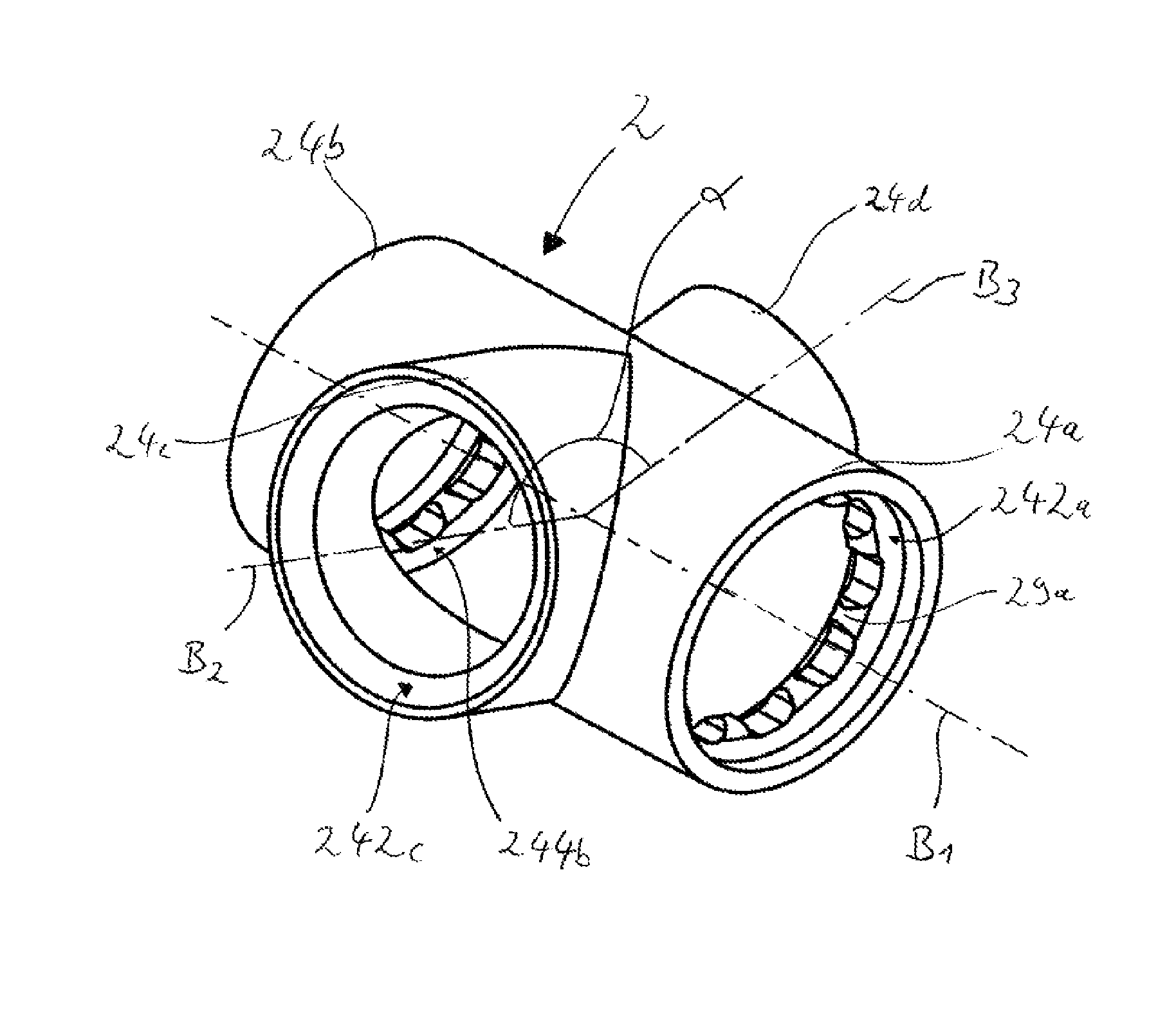
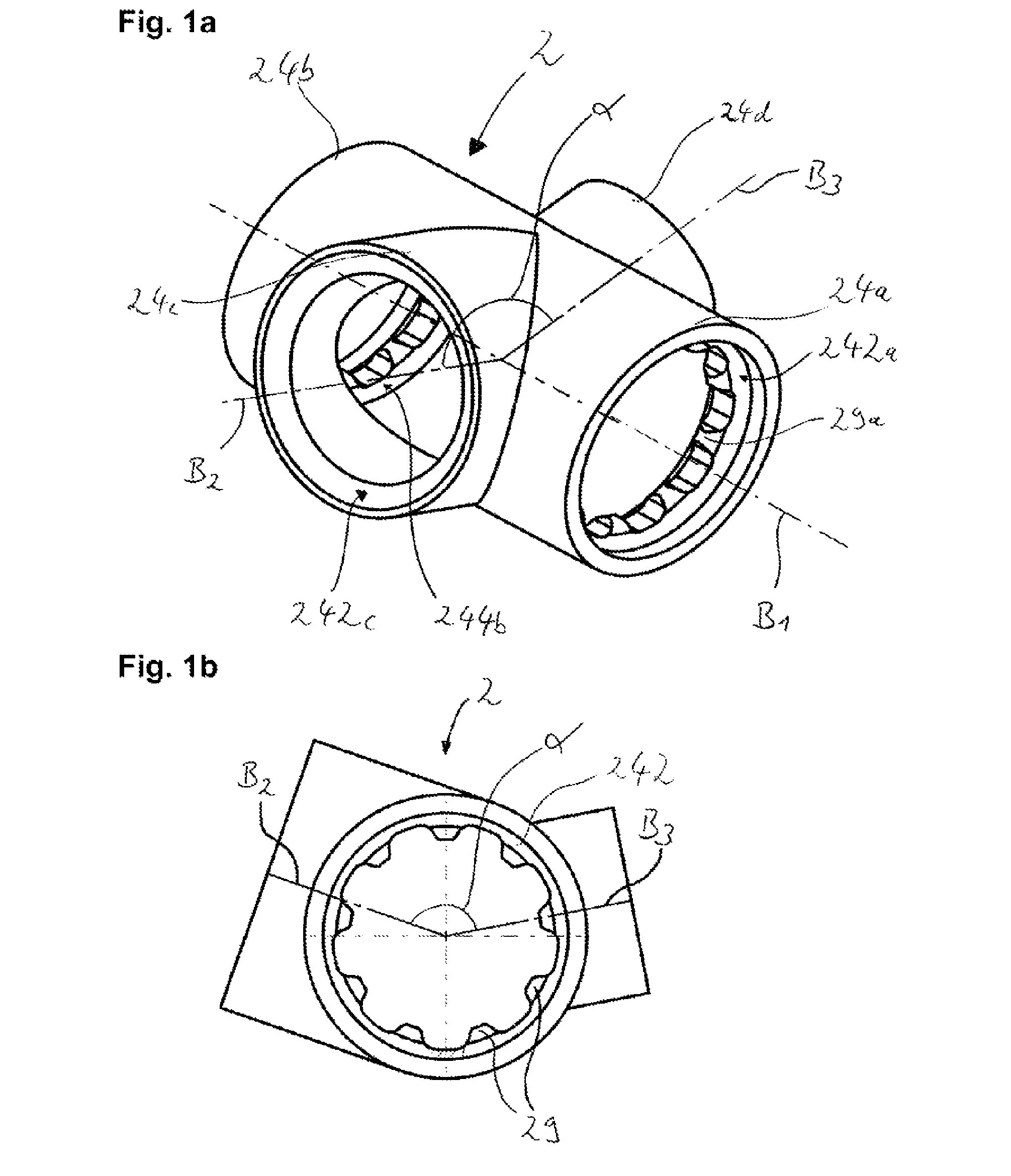
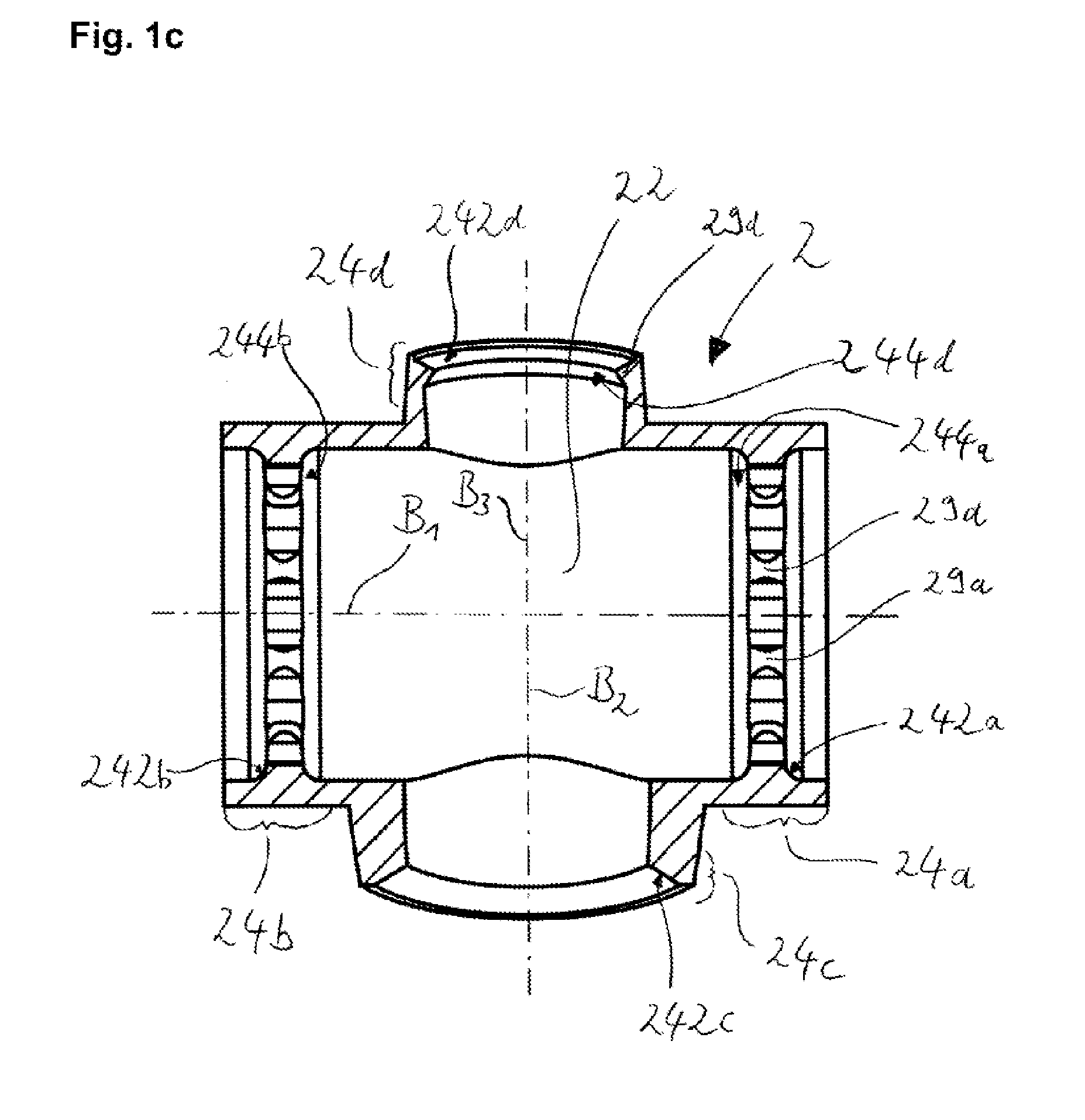
[0028]FIGS. 1a, 1b and 1c show different views of a first preferred embodiment of the axle link junction unit 2 according to the invention. It can be seen from the perspective view in FIG. 1a that the axle link junction unit has two, preferably four, attachment sections 24a, 24b, 24c and 24d. Below, geometries assigned to respective individual attachment sections, such as for example the abutment surface 242, will be assigned to one of the corresponding attachment sections 24 (a-d, . . . ) by way of the respectively corresponding letters a, b, c, . . . . The first attachment section 24a and the second attachment section 24b are preferably of rotationally symmetrical form, or substantially rotationally symmetrical form, about the first attachment axis B1. The third attachment section 24c is of substantially rotationally symmetrical form about the second attachment axis B2, and the fourth attachment section 24d is preferably of rotationally symmetrical form about the third attachment ...


PUM


Abstract

An axle link junction unit includes a base section and an attachment section, the base section comprising a hollow body at least in transitions into the attachment section along an attachment axis, the attachment section non-detachably fixing a support element to the axle link junction unit, wherein a second attachment section is arranged coaxially with respect to the first attachment section and is situated opposite the first attachment section, and wherein a third attachment section extends substantially along a second attachment axis and a fourth attachment section extends substantially along a third attachment.

Description

BACKGROUND OF THE INVENTION[0001]The present invention relates to an axle link junction unit for use in the running gear system of a utility vehicle.[0002]Axle link systems of utility vehicles are sufficiently well known from the prior art. Here, in the case of the hitherto known embodiments, the axle link or longitudinal link of a utility vehicle is fixed by means of a clamping connection to the axle body of the utility vehicle, wherein said connection is in most cases reinforced by means of a welded connection produced by thermal welding. In particular, it is the intention for the axle to be connected rotationally conjointly to the axle link by means of this doubly secured connection. It has been found that, owing to the local introduction of heat arising during the thermal welding process, temperature stresses can arise and cause weakening of the microstructure in the axle and in the longitudinal link. As a result, the connecting point between axle body and axle link is one of th...

Claims


Application Information

Patent Timeline
Patent Type & Authority Patents(United States)
IPC IPC(8): B60B35/00B60G9/00B60G7/00B60B35/02B60G21/05
CPCB60B35/02B60G7/00B60G9/003B60G21/051B60G2204/43B60G2206/20B60G2206/30
Inventor DREWES, OLAFBIEWER, FREDERIK
Owner SAF HOLLAND GMBH
Why Eureka
Try Eureka