
Sliding member

a technology of sliding member and sliding shaft, which is applied in the direction of coating, mechanical equipment, lubricant composition, etc., can solve the problems of affecting the sealing performance of the sealing shaft, the coating may not withstand the sliding of the rotating shaft, and the sealing performance may be significantly degraded, so as to achieve high wear resistance and reduce friction

Active Publication Date: 2016-12-20
JTEKT CORP
View PDF3 Cites 0 Cited by
  • Summary
  • Abstract
  • Description
  • Claims
  • Application Information

AI Technical Summary

Benefits of technology

The solution effectively reduces friction and maintains sealing performance by preventing cracking and peeling of the coating, thereby maintaining the sliding torque-reduction effect and ensuring appropriate sealing performance during high-speed sliding.

Problems solved by technology

However, when the conventional coating is used for the sliding member such as an oil seal, the coating may fail to withstand sliding of the rotating shaft or the like, which rotates at high speed, and crack in a short period of time or may be likely to be peel off in a short period of time due to insufficient adhesion to the oil seal, which serves as a base.
When the coating cracks, sealing performance may be significantly degraded in a short period of time based on a change in contact form resulting from the destruction of the base material.
Furthermore, when peel-off of the coating starts at the position of the crack, the capability of reducing friction is lost, and the sliding torque may increase significantly in a short period of time.

Method used


Image

  • Sliding member
  • Sliding member
  • Sliding member

Examples


Embodiment Construction

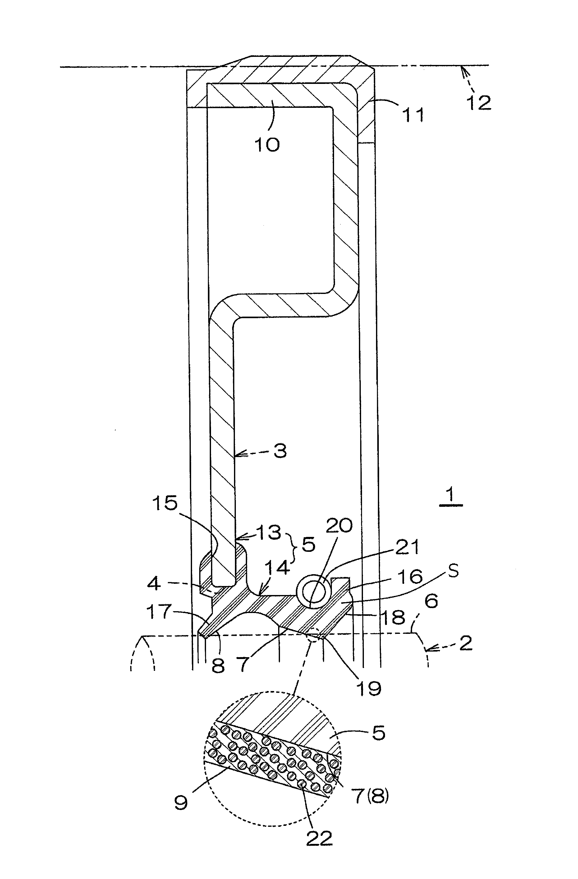
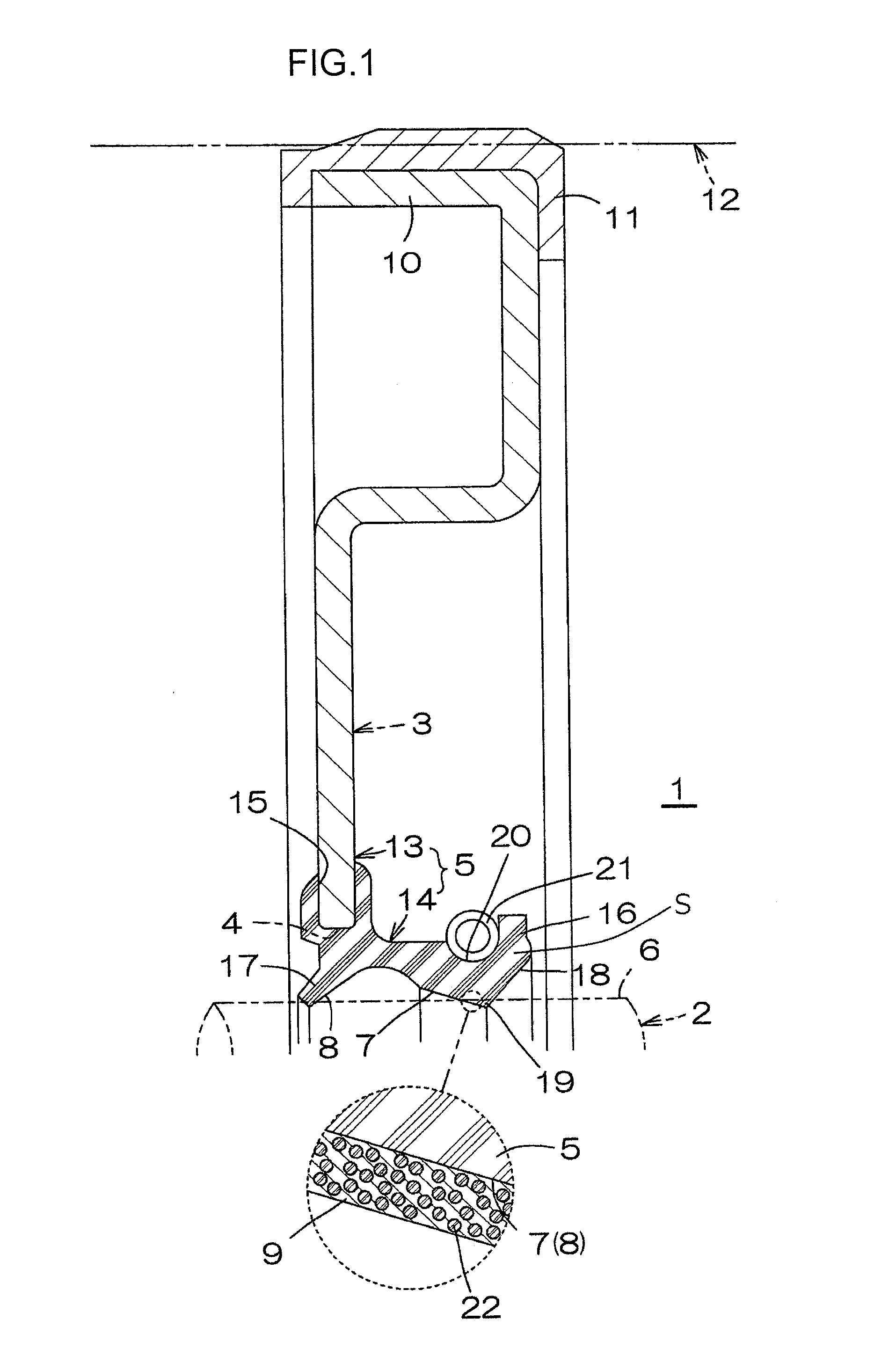
[0017]FIG. 1 is a sectional view of an oil seal as an example of an embodiment of a sliding member of the present invention. As seen in FIG. 1, the oil seal in this example is intended to seal a gap between a rotating shaft 2 as another member and a metallic ring 3 that is a ring surrounding the rotating shaft 2. A sliding member S included in the oil seal 1 includes a substrate 5 and a coating 9. The substrate 5 is secured to a radially inner end 4 of the metallic ring 3 and is integrally formed of fluorine rubber as a whole. The coating 9 covers tapered surfaces 7 and 8 of the substrate 5 that serve as sliding surfaces for an outer peripheral surface 6 of the rotating shaft 2.

[0018]The metallic ring 3 is fixedly fitted into a housing 12 surrounding the metallic ring 3 with a fitting portion 11 compressively deformed between the metallic ring 3 and the housing 12. The fitting portion 11 is secured to a radially outer end 10 of the metallic ring 3 and integrally formed of fluorine r...


PUM

PropertyMeasurementUnit
temperatureaaaaaaaaaa
particle sizeaaaaaaaaaa

Abstract

In a sliding member, a sliding surface of a substrate of fluorine rubber on which another member slides is covered with a coating that is formed of an epoxy resin having a scratch hardness (Pencil Method) after curing of F to 2H and in which fluorine resin powder is dispersed.

Description

INCORPORATION BY REFERENCE[0001]The disclosure of Japanese Patent Application No. 2014-183429 filed on Sep. 9, 2014 including the specification, drawings and abstract, is incorporated herein by reference in its entirety.BACKGROUND OF THE INVENTION[0002]1. Field of the Invention[0003]The invention relates to a sliding member used for an oil seal and the like.[0004]2. Description of Related Art[0005]An oil seal is assembled on a rotating shaft for an engine of an automobile in order to prevent, for example, leakage of oil through an end of the rotating shaft, and conversely, entry of external dust. The oil seal needs to be highly resistant to heat and oil. Thus, fluorine rubber is often used as a formation material for a sliding member used for the oil seal. For the oil seal, there has also been a request for a substantial reduction in sliding torque in order to meet recent demands for energy saving and an extended life of the oil seal.[0006]Thus, effort has been made to cover a slidi...

Claims


Application Information

Patent Timeline
Patent Type & Authority Patents(United States)
IPC IPC(8): C10M107/38F16J15/32C08J7/04C08J7/043C08J7/046
CPCC10M107/38C08J7/047F16J15/324F16J15/3284C08J2327/12C08J2427/12C08J2463/00C10N2220/082C10N2230/06C10N2250/12C08J7/0427C10N2020/06C10N2030/06C10N2050/015C08J7/043C08J7/046
Inventor KUNISHIMA, TAKESHIAMOH, TAKASHIMIYAMOTO, KEISUKEJIMBO, MASAKO
Owner JTEKT CORP
Learn More