Image forming apparatus with rotary polygon mirror speed control
a technology of polygon mirror and forming apparatus, which is applied in the direction of visual presentation using printers, instruments, electrographic processes, etc., can solve the problems of reducing the lifetime of the motor, requiring a long time to stabilize the rotation, and requiring a long time for the motor to rise from a stopped sta
- Summary
- Abstract
- Description
- Claims
- Application Information
AI Technical Summary
Benefits of technology
Problems solved by technology
Method used
Image
Examples
example 1
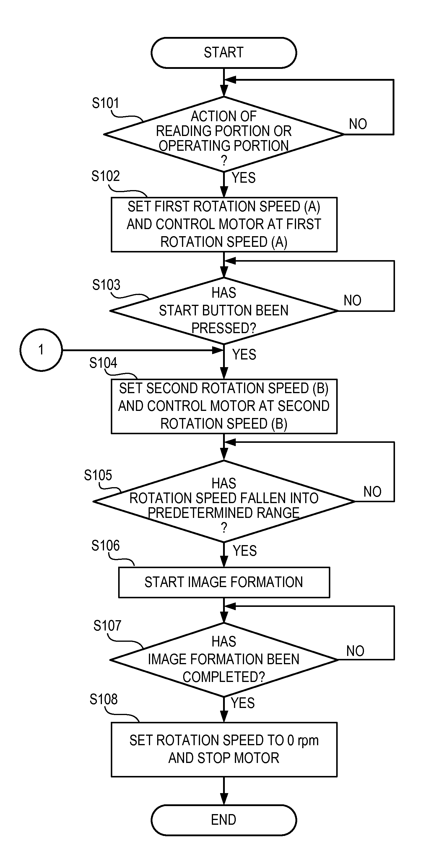
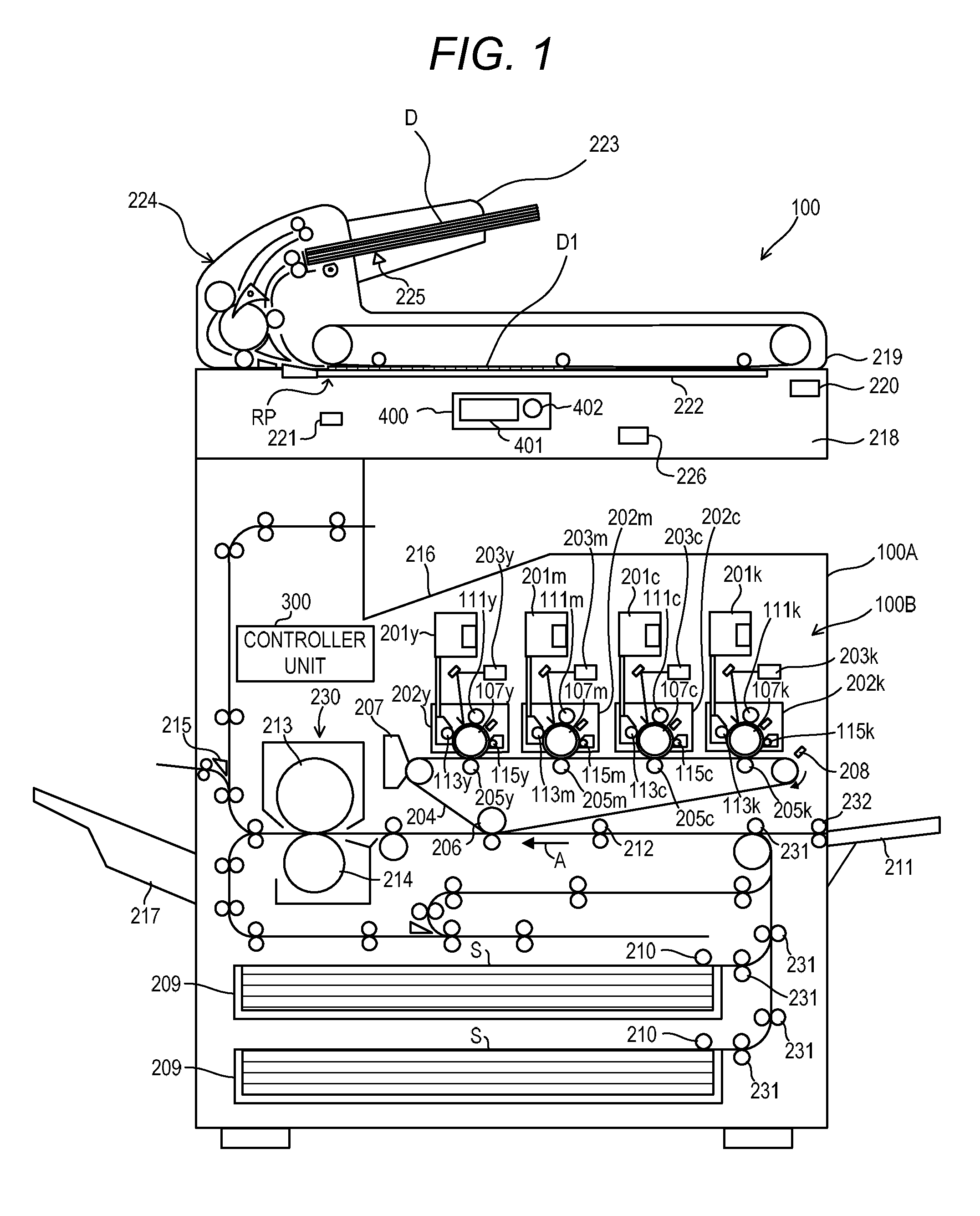
[0048]FIG. 4 is a diagram showing a relationship among timing charts and the rotation speed of the motor 102 in a case where the image formation is executed for the copy job in the image forming apparatus 100 according to the embodiment. Part (a) of FIG. 4 is a timing chart of an output pulse of the sensor (for example, the pressure plate opening and closing sensor 220) configured to detect a predetermined action performed on the reading device 218 or the operating portion 400. Part (b) of FIG. 4 is a timing chart of an output pulse of a sensor configured to detect that the start button 402 of the operating portion 400 is pressed. Part (c) of FIG. 4 is a timing chart of a trigger pulse generated when the print data is input to the print job data receiving portion 501. Part (d) of FIG. 4 is a graph showing a target rotation speed setting value of the motor 102 on a time axis.
[0049]In the case where the image formation of the copy job is executed, it is apparent that no print data is ...
example 2
[0054]Next, the other image forming operation (the image formation of the print job) according to the first embodiment will be described. In Example 1, the driving rotation speed of the motor 102 is set to the first rotation speed which is different from the rotation speed (the second rotation speed) for the image formation based on the operation of the reading device 218 or the operating portion 400, to thereby drive the motor 102. On the other hand, in Example 2, the image formation is performed in response to the reception of the print data 500 by the print job data receiving portion 501 illustrated in FIG. 3 from the external information device 502.
[0055]FIG. 6 is a diagram showing a relationship among timing charts and the rotation speed of the motor 102 according to Example 2. Part (a) of FIG. 6 is a timing chart of the output pulse of the sensor configured to detect the predetermined action (the input action of the image forming condition to the operating portion 400) perform...
PUM
 Abstract
Description
Claims
Application Information
 - R&D
- Intellectual Property
- Life Sciences
- Materials
- Tech Scout
- Unparalleled Data Quality
- Higher Quality Content
- 60% Fewer Hallucinations
Browse by: Latest US Patents, China's latest patents, Technical Efficacy Thesaurus, Application Domain, Technology Topic, Popular Technical Reports.
© 2025 PatSnap. All rights reserved.Legal|Privacy policy|Modern Slavery Act Transparency Statement|Sitemap|About US| Contact US: help@patsnap.com


