Motor and method of manufacturing motor

a manufacturing method and motor technology, applied in the direction of manufacturing stator/rotor body, magnetic circuit rotating parts, shape/form/construction, etc., can solve the problems of increasing the number of parts, increasing the number of noise generation, and increasing the energy loss of the reduction gear or the generation of noise, etc., to achieve smooth and stable rotation, reduce vibration and/or noise, and high torque

Active Publication Date: 2018-05-03
TOKYO MOTRONICS CO LTD
View PDF3 Cites 2 Cited by
  • Summary
  • Abstract
  • Description
  • Claims
  • Application Information

AI Technical Summary

Benefits of technology

[0039]Accordingly, in the motor according to the second aspect of the present invention, by adopting the design where the number of salient pole groups and / or the number of coil groups are / is not limited to 6 and are / is increased to 9, 12, 15, . . . 3m, it is possible to allow a force Fβ by which the rotor 20 is attracted toward the rotary axis RA is dispersed to m number of places. Accordingly, it is possible to provide the motor where vibration and / or noise are / is further reduced.
[0040]It is expected that a motor for direct driving can output a high torque at the time of starting the motor and at the time of operating the motor at a low speed and that the motor can acquire smooth and stable rotation.
[0041]The motor according to the present invention can output a high torque also at the time of starting the motor and at the time of operating the motor at a low speed, and can acquire smooth and stable rotation by suppressing vibration and pulsations of a cogging torque because of the following reasons (a) to (c). (a) The number of poles is relatively large. (b) The salient pole groups excited in the same phase are arranged as a pair at positions displaced from each other by 180° in terms of a mechanical angle. (c) The number of magnetic poles which the permanent magnet of the rotor has and the number of salient poles have a predetermined relationship (an arrangement pitch of the permanent magnet and an arrangement pitch of the salient poles have a predetermined relationship) and the like. Accordingly, with the invention described in the above-mentioned [10], it is possible to provide a motor suitable for direct driving.
[0042]According to the motor manufacturing method of the present invention, in the winding forming step, a plurality of coils belonging to the i-th coil group are formed collectively and in a continuously connected manner by being wound around the coil manufacturing tool. Then, in the i-th coil group shaping step, the coils are shaped in a state where the coil can be easily fitted into the salient pole. Then, in the coil fitting step, the shaped coils which are formed in a continuously connected manner are collectively fitted on the salient poles so that the coils are mounted on the salient poles. Accordingly, it is unnecessary to mount the coils in such a manner that windings are directly wound around salient poles while being pushed to bottoms of slots and hence, even when a width of the slot is narrow, the coil can be mounted on the salient pole easily and efficiently in the form suitable for mass production.
[0043]Further, with the motor manufacturing method according to the present invention, the formation of the j-th coil formed by winding the winding t times around the coil manufacturing tool, the formation of the j-th connecting wire by winding the winding half way around the coil manufacturing tool, the formation of the (j+1)th coil by winding the winding t times around the coil manufacturing tool, and the formation of the (j+1)th connecting wire by winding the winding halfway around the coil manufacturing tool are performed such that all coils are wound around a first rotational direction which is the same direction without changing the winding direction in the course of winding and hence, the winding forming step can be performed in the form suitable for efficient mass production.
[0044]With the motor manufacturing method described in the above-mentioned [12], in the j-th coil separation step, the size of the fitting portion is changed to a second size smaller than a first size maintained in the winding forming step thus narrowing a width of the fitting portion and hence, gap can be formed between an inner side of the coil and an outer side of the fitting portion. Accordingly, the separation of the coil can be performed easily and hence, the j-th coil separation step can be performed without collapsing a shape of the coil at the time of separating the coil and in the form suitable for further efficient mass production.

Problems solved by technology

However, this method additionally requires the reduction gear besides the motor and hence, the number of parts is increased whereby it is difficult to make the whole power mechanism small-sized and light-weighted.
Further, problems such as an energy loss in the reduction gear or the generation of noises also newly arise more or less.

Method used


Image

  • Motor and method of manufacturing motor
  • Motor and method of manufacturing motor
  • Motor and method of manufacturing motor

Examples


embodiment 1

1. Basic Structure of Motor 10 According to Embodiment 1

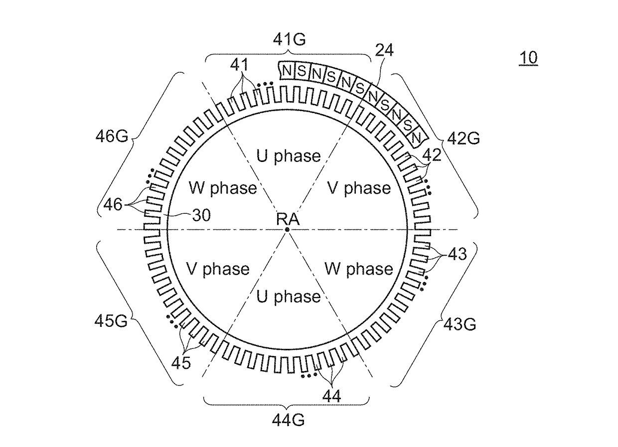
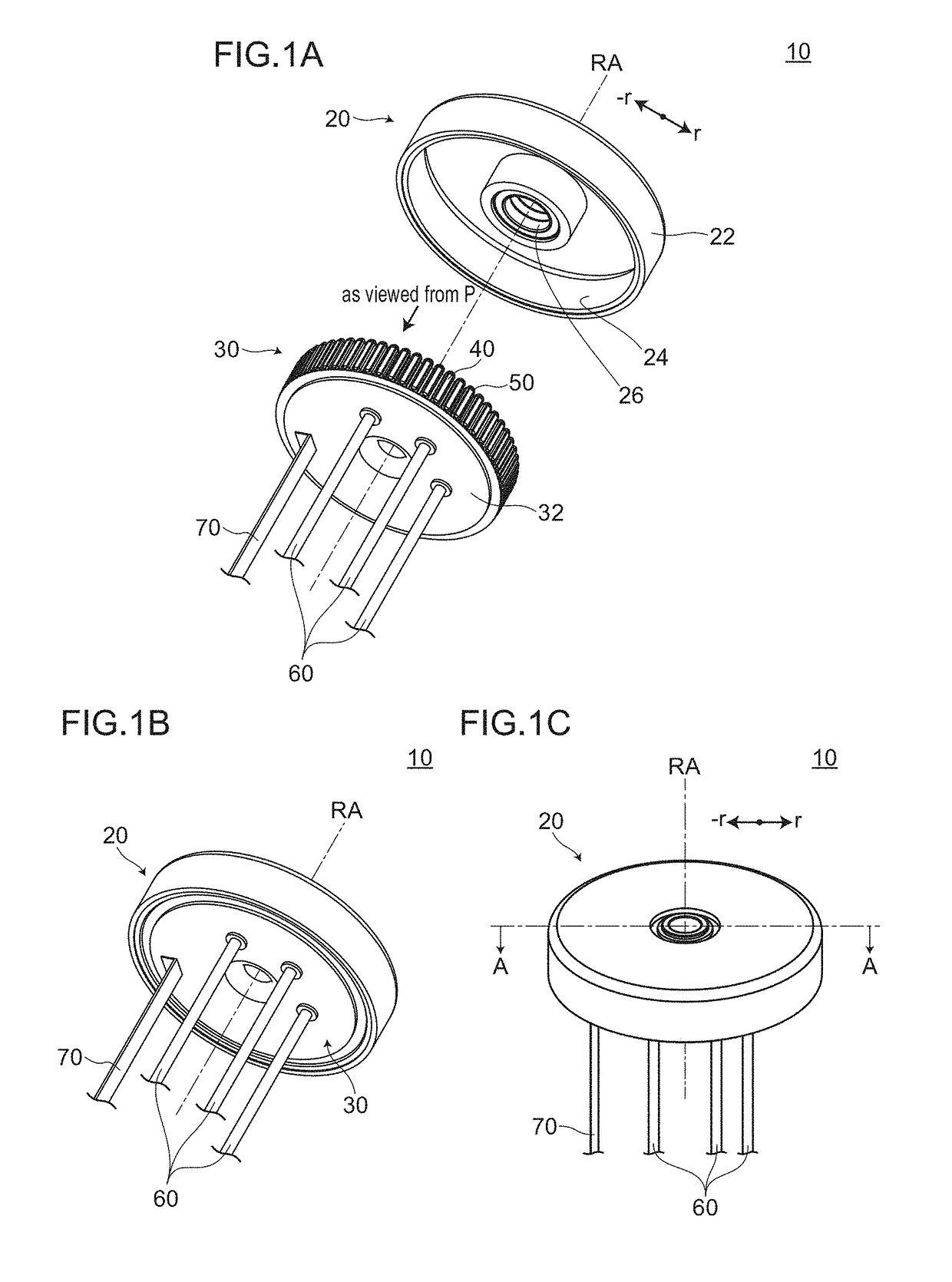
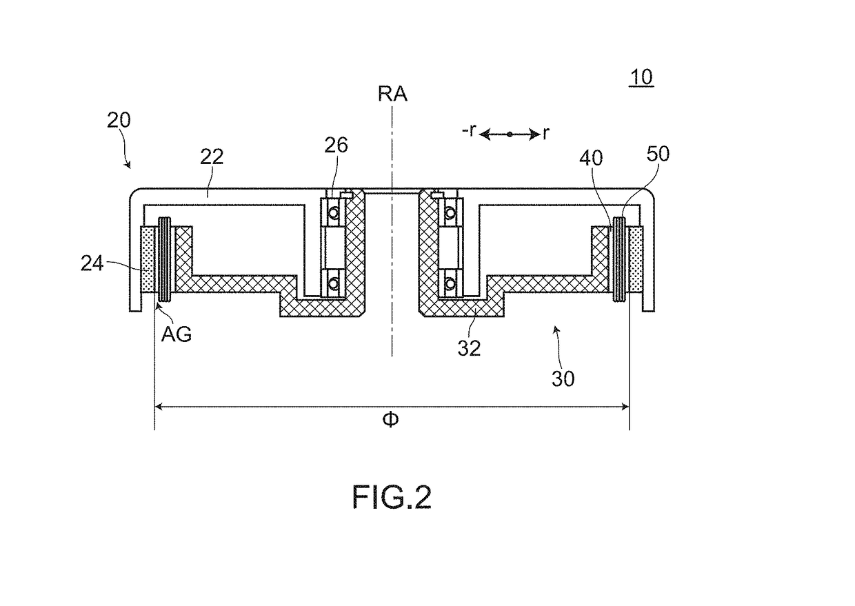
[0062]FIG. 1A to FIG. 1C, FIG. 2, FIG. 3A to FIG. 3B and FIG. 4A to FIG. 4B are views for describing a motor 10 according to an embodiment 1. FIG. 1A is a perspective view showing a state where the motor 10 is disassembled. FIG. 1B and FIG. 1C are perspective views showing a state where a rotor 20 and a stator 30 are assembled to each other. FIG. 2 is a cross-sectional view of the motor 10 taken along a plane A-A in FIG. 1C. FIG. 3A is a view showing an arrangement of salient poles 40 when the motor 10 is viewed in a plan view along a rotary axis RA. In FIG. 3A, a part of the permanent magnet 24 is also shown. Further, boundaries each of which is formed between each two salient pole groups among first salient pole group 41G to sixth salient pole group 46G are indicated by a dotted chain line respectively for the sake of convenience. FIG. 3B is a view showing the first salient pole group 41G, a first coil group 51G, and the perm...

embodiment 2

[0137]Hereinafter, a motor 12 according to an embodiment 2 is described.

[0138]FIG. 10 is a view for describing an arrangement relationship between salient poles 40 and a permanent magnet 24 of the motor 12 according to the embodiment 2. Boundaries between a first salient pole group 41G to a twelfth salient pole group 412G are indicated by a chained line for the sake of convenience. In FIG. 10, the description is made mainly with respect to the salient poles 40 and the permanent magnet 24, and the description of other constitutional elements such as coils is omitted.

[0139]Although the motor 12 according to the embodiment 2 basically has substantially the same configuration as the motor 10 of the embodiment 1, the motor 12 according to the embodiment 2 differs from the motor 10 according to the embodiment 1 with respect to the number of salient poles, the number of coils and the like. That is, as shown in FIG. 10, the motor 12 according to the embodiment 2 includes twelve salient pole...

embodiment 3

[0164]Hereinafter, a motor 13 according to an embodiment 3 is described.

[0165]FIG. 13 is a view for describing an arrangement relationship between salient poles 40 and a permanent magnet 24 of the motor 13 according to the embodiment 3. Boundaries between a first salient pole group 41G to a ninth salient pole group 49G are indicated by a chained line for the sake of convenience. In FIG. 13, the description is made mainly with respect to the salient poles 40 and the permanent magnet 24, and the description of other constitutional elements such as coils is omitted.

1. Configuration of Motor 13 According to Embodiment 3

[0166]Although the motor 13 according to the embodiment 3 basically has substantially the same configuration as the motor 12 according to the embodiment 2, the motor 13 according to the embodiment 3 differs from the motor 12 according to the embodiment 2 with respect to the number of salient pole groups, the number of coil groups and the like. That is, as shown in FIG. 13...


PUM


Abstract

A motor includes: a rotor having a permanent magnet and a stator having salient poles with coils. First to sixth salient pole groups each having n salient poles are arranged along a circumferential direction. The salient pole groups to which electric currents of the same phase are supplied are displaced from each other by 180 degrees in mechanical angle. Each salient pole has a straight shape. A coil group on the salient poles of each salient pole group is formed by connecting the n coils in series, winding directions of the coils of adjacent salient poles are opposite to each other, the coils are connected to each other at a distal or a proximal end side of the salient pole by a connecting wire between the adjacent salient poles, and the connecting wires have a reverse relationship with respect to the distal or the proximal end side between adjacent slots.

Description

TECHNICAL FIELD[0001]The present invention relates to a motor and a method of manufacturing a motor.BACKGROUND ART[0002]A power mechanism which incorporates a motor therein has been positively used in various vehicles, equipment and the like. Particularly, with respect to a power mechanism used in an applied product such as an electric vehicle such as a wheelchair, an electric stand-on two-wheeled vehicle (for example, Segway (registered trademark)) or the like, a nursing care robot or an electric reel for fishing, there has been a demand for a power mechanism which is small-sized and light-weighted but can output a high torque.[0003]As a method for enabling a power mechanism to output a high torque, a method which uses a reduction gear is named as one example. In this method, a reduction gear which has a plurality of gears is connected to an output shaft (shaft) of a motor so that rotational speed produced by the motor is reduced whereby power whose torque is increased is transmitt...

Claims


Application Information

Patent Timeline
Patent Type & Authority Applications(United States)
IPC IPC(8): H02K1/24H02K1/27H02K1/26H02K21/16H02K15/03
CPCH02K1/24H02K1/274H02K1/265H02K21/16H02K15/03H02K2213/03H02K3/18H02K15/085H02K21/22H02K1/146
Inventor HASEBE, YOICHIKODAIRA, TOMOYUKI
Owner TOKYO MOTRONICS CO LTD
Why Eureka
Try Eureka