Collapsible roll-out truss

a roll-out truss and collapsible technology, applied in the direction of girders, transoms, cosmonautic vehicles, etc., can solve the problems of large stowed volume, lack of rigidity and precision of structure, and disadvantages of both conventional structural elements

Active Publication Date: 2016-12-27
TENDEG
View PDF53 Cites 17 Cited by
  • Summary
  • Abstract
  • Description
  • Claims
  • Application Information

AI Technical Summary

Benefits of technology

[0009]Accordingly, a broad object of the invention can be to provide generic structural units which can be interconnected to form a wide variety of collapsible structures which interconvert between a deployed condition and a flat condition and can be further interconverted between the flat condition and a rolled condition to reduce a stowed volume.
[0012]Another broad object of the invention can be to provide a method of making generic structural units useful in producing a variety of collapsible structures which include longerons configurable between a substantially flat condition and a substantially tubular condition maintained in substantially fixed spaced apart relation by a plurality of cross members which as to particular embodiments can be secured between longerons to form alternately inverted triangle-shaped open spaces providing truss-like mechanics in the deployed condition of the generic structural units and overall as to the collapsible structure.

Problems solved by technology

However, both of these conventional structural elements have disadvantages.
The conventional and deployable rigid truss structure includes a copious number of longerons, battens and diagonals having numerous corresponding joints that individually and collectively can include substantial deadband (range of movement in which no action occurs) and therefore the structure may lack stiffness and precision.
Additionally, trusses often stack sequentially bay by bay onto themselves which can result in a relatively large stowed volume.
The high part count and precision assembly requirements make conventional deployable truss structures expensive.
However, STEMs typically deploy as a slit tube structure which may lack sufficient buckling capacity and torsional stiffness to act as a support in large structures.
Because of the lack of buckling and torsional stiffness, STEM structures can be scale limited.

Method used


Image

  • Collapsible roll-out truss
  • Collapsible roll-out truss
  • Collapsible roll-out truss

Examples


Embodiment Construction

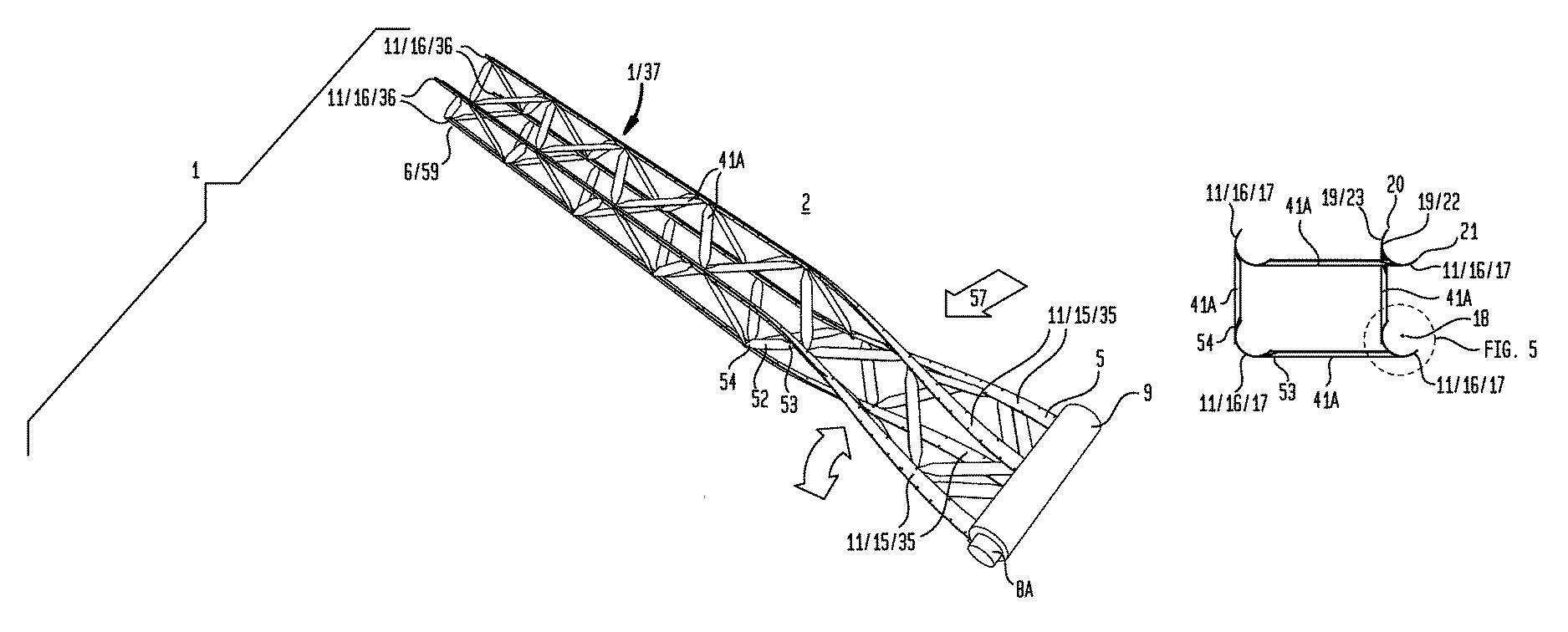
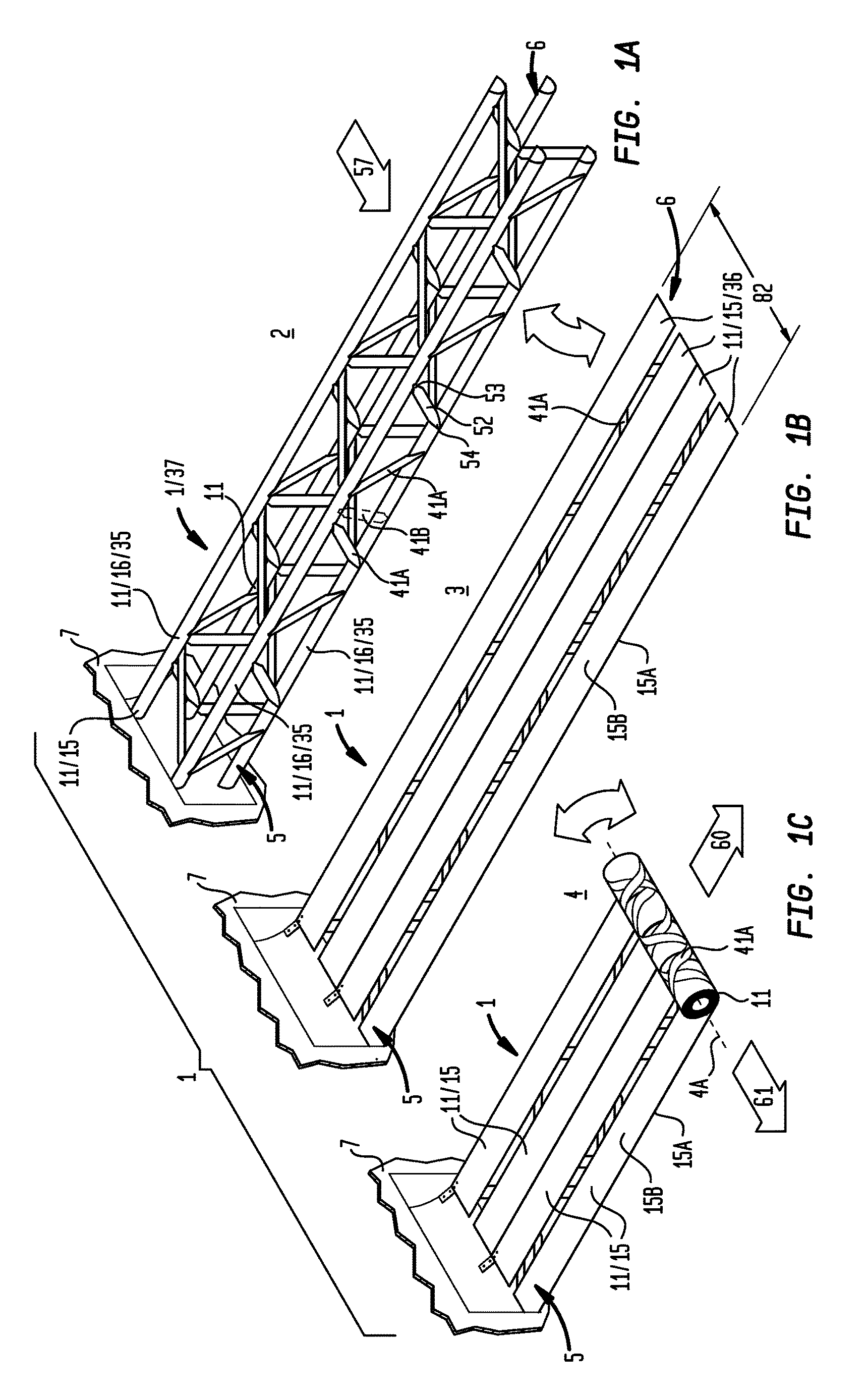
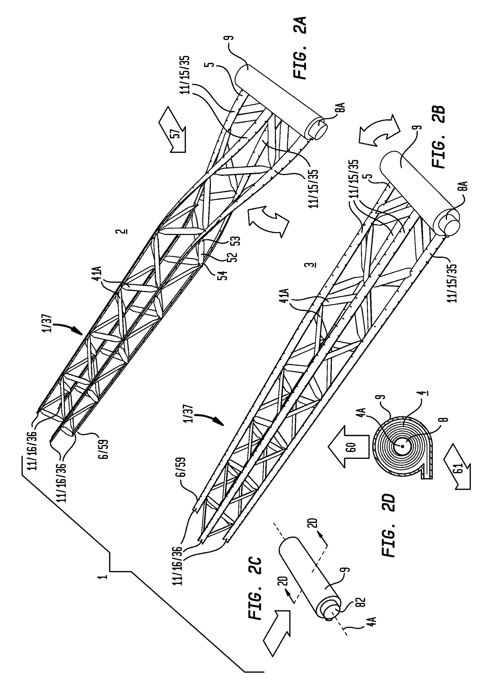
[0084]Generally referring to FIGS. 1 through 57, illustrative examples are shown of embodiments of an inventive collapsible structure (1) which interconvert between a deployed condition (2) and a planate condition (3) (as shown in the examples of FIGS. 1A and 1B and FIGS. 2A and 2B). The planate condition (3) of embodiments of the collapsible support structure (1) can further interconvert between the planate condition (3) and a rolled condition (4) to reduce the volume of the collapsible structure (as shown in the examples of FIG. 1C and FIGS. 2B through 2D). The rolled condition (4) of embodiments of the collapsible structure (1) can be achieved by concentrically winding or coiling the planate condition (3) from either a root end (5) or a tip end (6) of the collapsible structure (1). The planate condition (3) can store sufficient mechanical energy during conversion from the deployed condition (2) to the planate condition (3) to convert the planate condition (3) toward the deployed ...


PUM

PropertyMeasurementUnit
constant poweraaaaaaaaaa
pressureaaaaaaaaaa
angleaaaaaaaaaa

Abstract

Collapsible support structures and methods of making collapsible support structures which interconvert between a deployed condition and a collapsed planate condition which allows extensible retractable deployment of the collapsed structure from a reduced volume rolled condition.

Description

[0001]This application is the United States National Stage of International Patent Cooperation Treaty Patent Application No. PCT / US2014 / 016605, filed Feb. 14, 2014, which claims the benefit of U.S. Provisional Patent Application No. 61 / 765,641, filed Feb. 15, 2013, each hereby incorporated by reference herein.I. TECHNICAL FIELD[0002]Collapsible structures and methods of making collapsible structures which interconvert between a deployed condition and a collapsed planate condition which allows extensible retractable deployment of the collapsed support structure from a reduced volume rolled condition.II. BACKGROUND[0003]There is a need for large-mass efficient support structures which interconvert between a reduced volume stowed condition and a deployed condition having sufficient axial, bending and torsional stiffness to support blanket arrays, such as blanket solar arrays on orbit, and for other applications.[0004]As one example, NASA's Solar Array Structures Program has embarked on...

Claims


Application Information

Patent Timeline
Patent Type & Authority Patents(United States)
IPC IPC(8): E04C3/00B32B5/26E04C3/02B64G1/22B64G99/00E04C3/28E04C3/46E04C3/36E04C3/29
CPCE04C3/005B32B5/26B64G1/222B64G9/00E04C3/02E04C3/28E04C3/291E04C3/36E04C3/46B32B2419/00E04C2003/023E04C2003/026B64G99/00
Inventor FREEBURY, GREGG E.FRANCIS, WILLIAM H.
Owner TENDEG
Why Eureka
Try Eureka