Ice auger reversal attachment

a technology of reversal attachment and ice auger, which is applied in the direction of ice drilling, drilling machines and methods, earthwork drilling and mining, etc., can solve the problems of only operating the augers available on the market, affecting fishing, and excessive slush around the hole opening, etc., and achieves efficient transition

Active Publication Date: 2016-12-27
DOSTAL THOMAS JAMES
View PDF17 Cites 8 Cited by
  • Summary
  • Abstract
  • Description
  • Claims
  • Application Information

AI Technical Summary

Benefits of technology

[0010]The invention generally relates to an ice auger reversal attachment which includes a mounting assembly adapted to be mounted to an ice auger motor. The mounting assembly includes a locking assembly which is adapted to selectively engage / disengage with an auger reversal assembly which is secured between the ice auger motor and the ice auger blade. Using the locking assembly and auger reversal assembly, the direction of rotation of the ice auger blade may be efficiently transitioned between a forward and reverse direction to aid in removal of slush when drilling a hole through a layer of ice.

Problems solved by technology

While the conventional methods of such auger use have been utilized for many years, it has been shown that merely pulling out a stationary ice auger blade from a drilled hole results in excessive slush around the hole opening.
This can be detrimental to fishing.
However, many ice augers available on the market only operate in a single direction.

Method used


Image

  • Ice auger reversal attachment
  • Ice auger reversal attachment
  • Ice auger reversal attachment

Examples


Embodiment Construction

A. Overview.

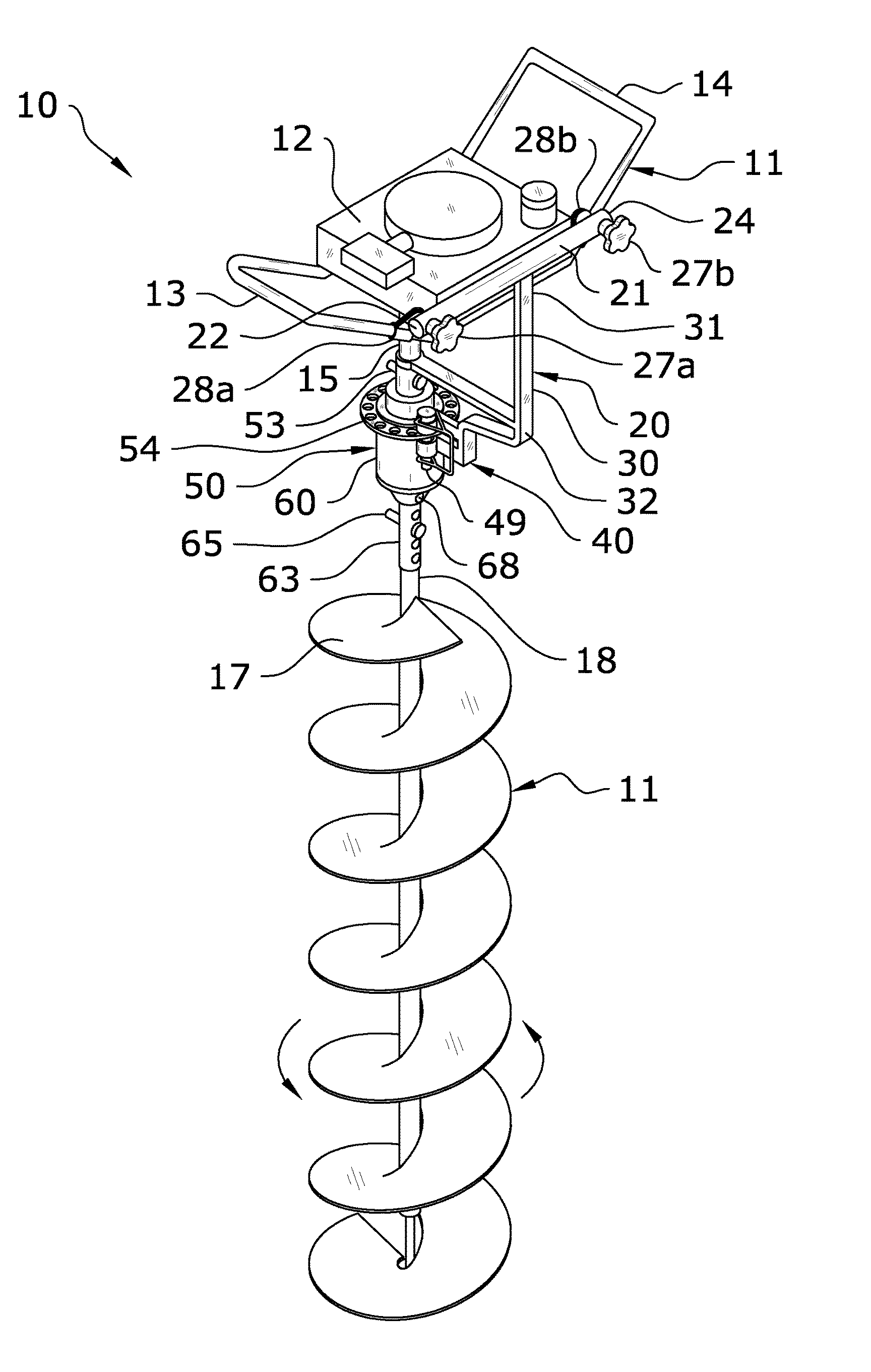
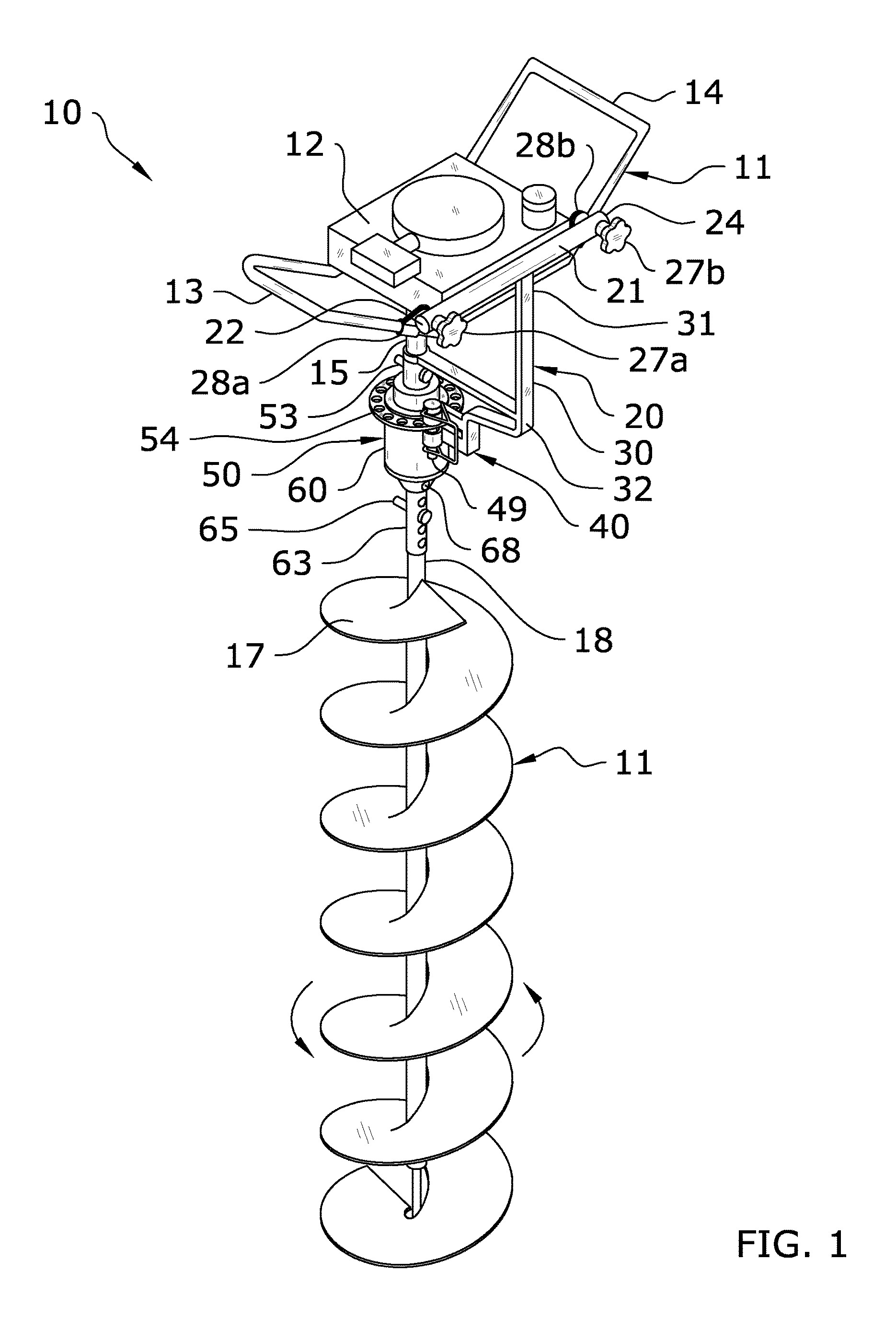
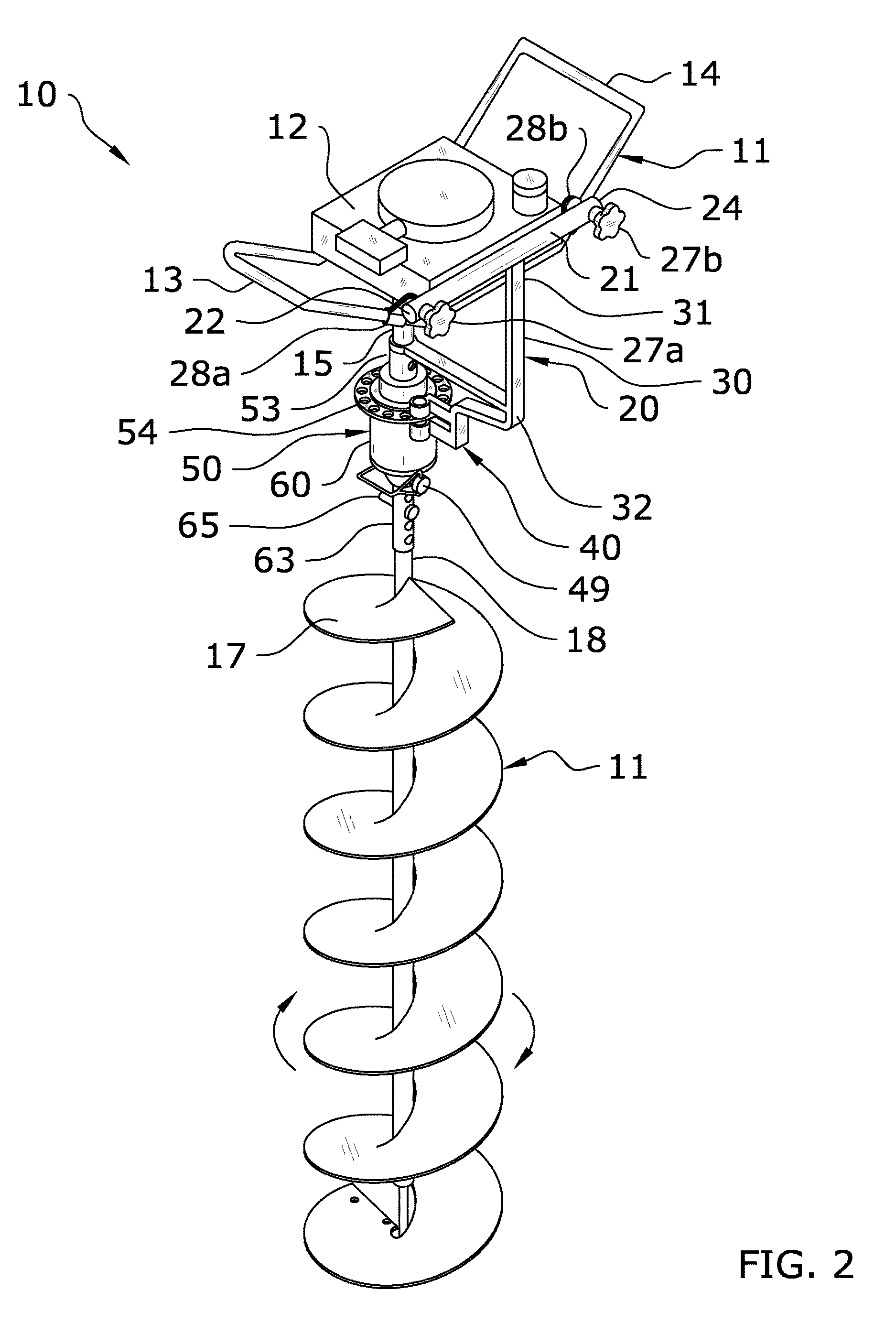
[0023]Turning now descriptively to the drawings, in which similar reference characters denote similar elements throughout the several views, FIGS. 1 through 10 illustrate an ice auger reversal attachment 10, which comprises a mounting assembly 20 adapted to be mounted to an ice auger motor 12. The mounting assembly 20 includes a locking assembly 40 which is adapted to selectively engage / disengage with an auger reversal assembly 50 which is secured between the ice auger motor 12 and the ice auger blade 17. Using the locking assembly 40 and auger reversal assembly 50, the direction of rotation of the ice auger blade 17 may be efficiently transitioned between a forward and reverse direction to aid in removal of slush when drilling a hole through a layer of ice.

B. Ice Auger.

[0024]As shown throughout the figures, the present invention is adapted to be installed in-line on an ice auger 11 between the ice auger motor 12 and the ice auger blade 17. It should be appreciated that ...


PUM


Abstract

An ice auger reversal attachment which couples in-line with an ice auger to selectively reverse direction of the ice auger blade. The ice auger reversal attachment generally includes a mounting assembly adapted to be mounted to an ice auger motor. The mounting assembly includes a locking assembly which is adapted to selectively engage/disengage with an auger reversal assembly which is secured between the ice auger motor and the ice auger blade. Using the locking assembly and auger reversal assembly, the direction of rotation of the ice auger blade may be efficiently transitioned between a forward and reverse direction to aid in removal of slush when drilling a hole through a layer of ice.

Description

CROSS REFERENCE TO RELATED APPLICATIONS[0001]Not applicable to this application.STATEMENT REGARDING FEDERALLY SPONSORED RESEARCH OR DEVELOPMENT[0002]Not applicable to this application.BACKGROUND OF THE INVENTION[0003]Field of the Invention[0004]The present invention relates generally to an ice auger attachment and more specifically it relates to an ice auger reversal attachment which couples in-line with an ice auger to selectively reverse direction of the ice auger blade.[0005]Description of the Related Art[0006]Any discussion of the related art throughout the specification should in no way be considered as an admission that such related art is widely known or forms part of common general knowledge in the field.[0007]Ice augers are commonly used in colder environments to drill holes through thick ice. Perhaps the most common usage of an ice auger is for ice fishing, in which a hole is drilled through thick ice to allow a fishing line to enter the underlying body of water. The conve...

Claims


Application Information

Patent Timeline
Patent Type & Authority Patents(United States)
IPC IPC(8): E21B7/00E21B10/44
CPCE21B7/008E21B10/44
Inventor DOSTAL, THOMAS JAMES
Owner DOSTAL THOMAS JAMES
Why Eureka
Try Eureka