Integrating sphere type device with specular control

a technology of integrating spheres and spheres, applied in measurement devices, material analysis through optical means, instruments, etc., can solve the problems of uneven reflection of filler plugs, less accurate measurement of radiance of highly mirror-like surfaces,

Active Publication Date: 2016-12-27
WESTBORO PHOTONICS
View PDF5 Cites 1 Cited by
  • Summary
  • Abstract
  • Description
  • Claims
  • Application Information

AI Technical Summary

Benefits of technology

[0007]Accordingly, the present invention relates to a light integrating cavity device (LICD) for measurement of diffuse light reflectance of a sample, which comprises a shell enclosing a light scattering cavity (LSC) defined by an internal light scattering surface of the shell, and a light source disposed for illuminating the internal light scattering surface of the shell for creating scattered light within the LSC for illuminating the sample therewith. The shell has an aperture for allowing light out of the light scattering cavity for illuminating the sample when the sample is positioned at the aperture outside of the LSC, or for illuminating a light measurement device (LMD) with the scattered light reflected from, or transmitted through, the sample when the LMD is positioned outside of the LSC facing the aperture. A light trap is further provided that is mounted within the LSC and is rotatable to be in a specular optical alignment with the sample and the LMD, so as to prevent the LMD from receiving specular reflections from the sample.
[0008]Another aspect of the present invention relates to a method of measuring a diffuse light reflectance of a sample using a light integrating cavity device for providing diffuse light upon the sample and a light measurement device for measuring reflectance of the diffuse light from the sample, the method comprising: a) providing a movable light trap within a light integrating cavity of the light integrating cavity device, and b) moving the light trap to a position of a specular alignment with the sample and the light measurement device so as to prevent the light measurement device from receiving specular reflections from the sample.

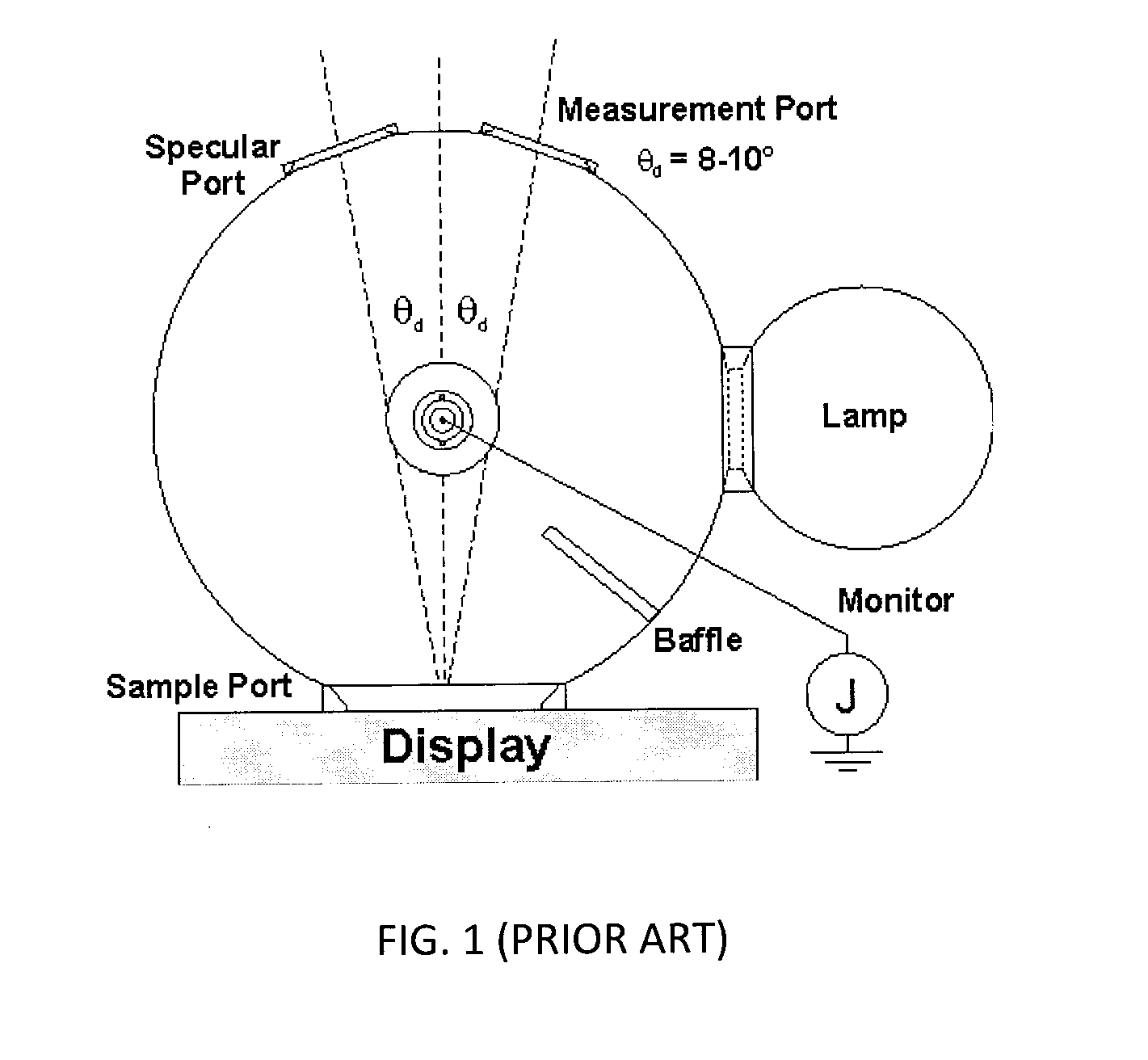
Problems solved by technology

This design has several limitations, including the following: a) only fixed angles of diffuse reflectance with the specular component excluded can be measured, b) the reflectance of the filler plugs may not be uniformly matched to the sphere wall and c) the radiance for highly mirror-like surfaces may be less accurately measured when the specular region is aligned to this non-uniform filler plug.

Method used


Image

  • Integrating sphere type device with specular control
  • Integrating sphere type device with specular control
  • Integrating sphere type device with specular control

Examples


Embodiment Construction

[0022]In the following description, for purposes of explanation and not limitation, specific details are set forth, such as particular circuits, sub-systems, optical and circuit components, mechanical elements, assemblies, or techniques, etc. in order to provide a thorough understanding of the present invention. However, it will be apparent to one skilled in the art that the present invention may be practiced in other embodiments that depart from these specific details. In other instances, detailed descriptions of well-known methods, devices, and tools are omitted so as not to obscure the description of the present invention.

[0023]Note that as used herein, the terms “first”, “second” and so forth are not intended to imply sequential ordering, but rather are intended to distinguish one element from another unless explicitly stated.

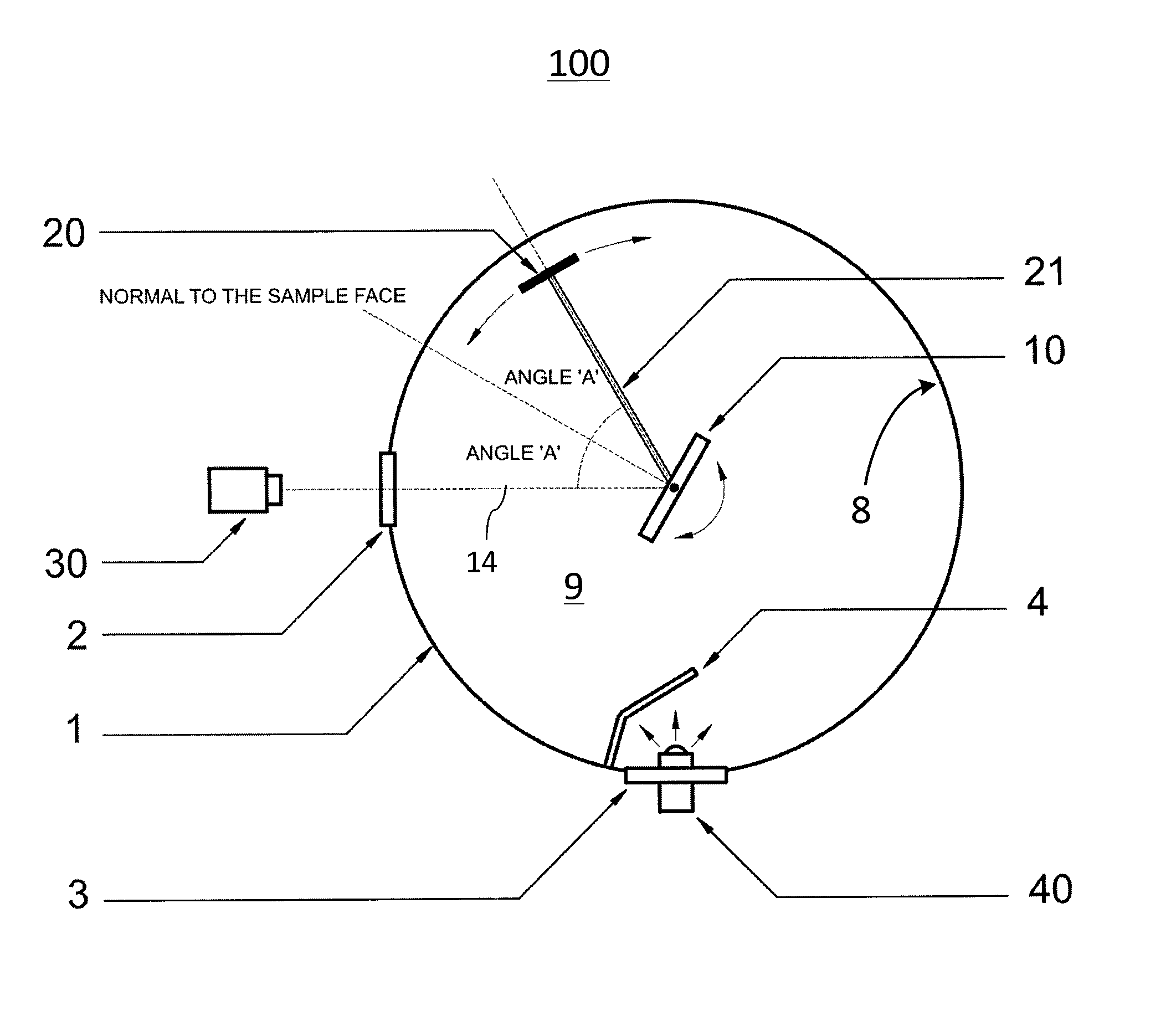
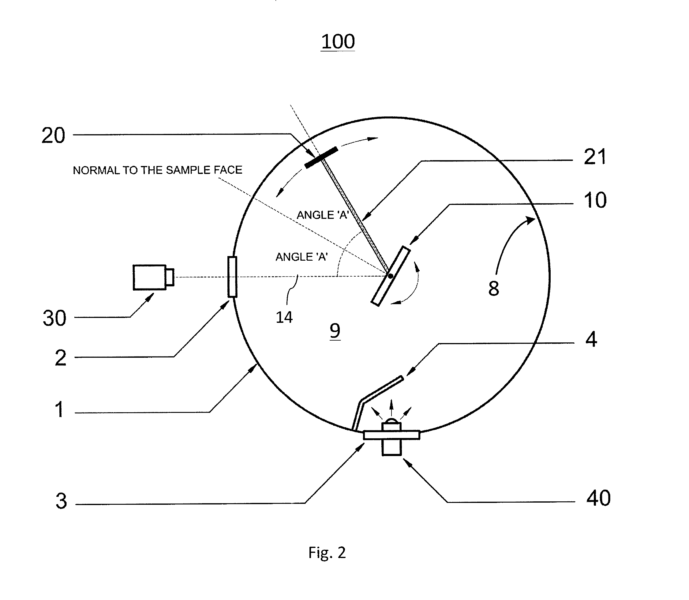
[0024]With reference to FIG. 2, there is shown a schematic top view of an integrating sphere type device (ISTD) 100 representing one exemplary “whole spher...


PUM

PropertyMeasurementUnit
angular rotationaaaaaaaaaa
diffuse light reflectanceaaaaaaaaaa

Abstract

The invention relates to a light integrating cavity device, such as an integrating sphere, for measuring diffuse reflectance of a sample. A light trap is movable within a light scattering cavity of the device for controlling specular reflections during measurements. The light trap may be rotatable around the sample under test inside the cavity so that specular reflections off the sample can be included or excluded from the measurement. The sample may also be placed at the outside against a measurement port, and a measurement instrument is moveable on a rotating arm within or outside of the cavity.

Description

RELATED APPLICATION DATA[0001]This application is the national stage entry of International Appl. No. PCT / CA2014 / 000026, filed Jan. 16, 2014, which claims priority to U.S. Provisional Patent Application No. 61 / 753,036, filed Jan. 16, 2013. All claims of priority to these applications are hereby made, and each of these applications is hereby incorporated in its entirety by reference.TECHNICAL FIELD[0002]The present invention generally relates to an integrating sphere type device for reflectance measurements, and more particularly to such a device which includes a light trap within a light scattering cavity for measuring diffuse reflectance with the specular component included or excluded.BACKGROUND OF THE INVENTION[0003]An integrating sphere is an optical component that is formed of a hollow spherical or hemispherical cavity with its interior covered with a diffusely reflecting coating. The integrating sphere normally has holes on the sphere wall for measurement and for illumination ...

Claims


Application Information

Patent Timeline
Patent Type & Authority Patents(United States)
IPC IPC(8): G01N21/00G01N21/47
CPCG01N21/4738G01N2201/065G01N2201/0642
Inventor MOGGRIDGE, TIM
Owner WESTBORO PHOTONICS
Why Eureka
Try Eureka