Illuminator for inspecting substantially flat surfaces

a flat surface, illumination technology, applied in the direction of optically investigating flaws/contamination, mirrors, instruments, etc., can solve the problems of insufficient long life of conventional arrays and illuminators, inability to ensure the smooth blend of on-axis illumination and off-axis illumination, and inability to accurately detect the entire board. , to achieve the effect of reducing the noise ratio, reducing the noise, and reducing the amount of ligh

Inactive Publication Date: 2006-07-13
ORBOTECH LTD
View PDF71 Cites 0 Cited by
  • Summary
  • Abstract
  • Description
  • Claims
  • Application Information

AI Technical Summary

Benefits of technology

[0019] Prior art systems provide for either such adjustability or for a seamless illumination. As indicated above, such seamless illumination is desirable to avoid artifacts in images of printed circuit boards. Separate variation of on-axis and off-axis illumination is desirable to allow for adjustment of the two separate illuminations to achieve a uniform level of lighting, or to account for various reflectivities and roughness of the objects being imaged. For example, when viewing photomasks, in which black lines are formed on a clear substrate and the substrate is imaged against a matte surface, optimal contrast is achieved when the on-axis illumination is zero to avoid specular reflection from the “black” lines which reflect weakly, but specularly. Additionally, the signal to noise ratio of images of printed circuit boards may be optimized by reducing the intensity of off-axis illumination relative to the on-axis illumination. This is the result of an increase in reflection from the non-conducting portions of the boards and a decrease in mottling as off-axis illumination is increased.
[0024] Furthermore, prior art systems with non-normal on-axis illumination provided illumination from substantially all directions above the surface being illuminated (except for the direction of the imaging system). The present inventors have determined that it is desirable to limit the extent of off-axis illumination, at least when viewing printed circuit boards, since, while the mottle is decreased with increasing angle of illumination, the signal from the non-metallic portions of the workpiece increases faster than that from the metallic portion, resulting in a reduction in signal to noise ratio.
[0025] One aspect of some preferred embodiments of the present invention provides an illuminator for providing a wide solid angle of continuous concentrated illumination, comprising fewer optical elements than many prior art broad angle concentrating illuminators and / or less complicated construction of the parts.
[0026] Another aspect of some preferred embodiments of the present invention provides for a smooth seamless off-axis illumination and seamless blending of on-axis and off-axis illumination in an illuminator providing wide solid angle of continuous illumination, even when the intensities of the on-axis and off-axis sources are different.
[0027] Another aspect of some preferred embodiments of the present invention provides an illuminator that can provide wide solid angle of concentrated illumination for strips on the surface of a workpiece that are longer than strips that are illuminated by prior wide solid angle concentrating illuminators. This is made possible, in some measure, by the simplification in construction of the parts used in the system and in their alignment.

Problems solved by technology

A fault in any intermediate layer of the board may result in malfunction of the entire board.
Such conventional arrays and illuminators are typically insufficiently long to acquire an image of the entire width of the printed circuit board in a single pass.
This makes it difficult to assure that on-axis illumination and off-axis illumination are smoothly blended to provide a substantially uniform illumination throughout the broad angle of illumination over the area of an illuminated strip.
As a result of these difficulties, mechanical and optical components of prior art concentrated illuminators require very tight tolerances and are relatively expensive.
Furthermore these difficulties have restricted the lengths of the effective region of illumination to the order of 15 cm, which length is often less than the width of the board being inspected.
This system provides uneven off-axis illumination of the line on the board and does not allow for independent adjustment of on-axis and off-axis illumination since only a single source is used for illuminating the board from all directions.

Method used


Image

  • Illuminator for inspecting substantially flat surfaces
  • Illuminator for inspecting substantially flat surfaces
  • Illuminator for inspecting substantially flat surfaces

Examples


Embodiment Construction

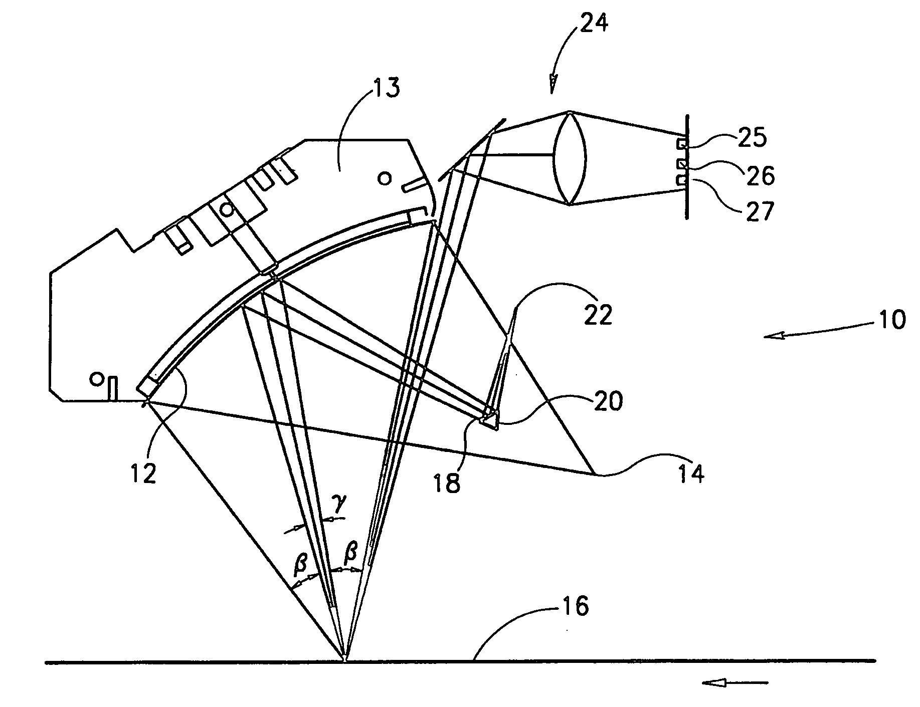
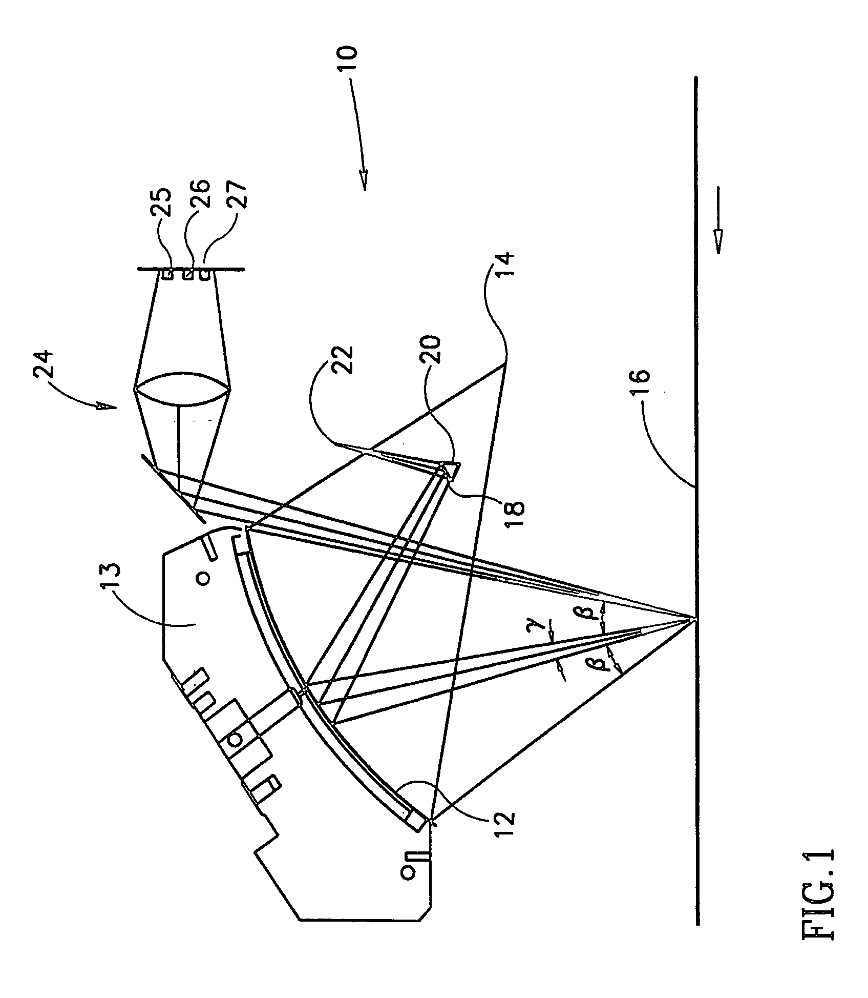
[0090]FIG. 1 shows a perspective view of a simplified schematic of an illuminator 10, in accordance with a preferred embodiment of the present invention. Illuminator 10 comprises a cylindrical reflector or mirror 12 having a substantially elliptical shape and a limited extent with an off-axis substantially uniform linear source of illumination 14 placed at one focus thereof and a workpiece or other substrate 16, to be optically examined placed at another focus thereof. A front surface strip mirror 18 is placed between off-axis source 14 and mirror 12, with the mirrored surface facing away from off-axis source 14. The width of strip mirror 18 is such that it allows light from off-axis source 14 to be concentrated by mirror 12 and to reach substrate 16 from two angular sectors each having a width β each as shown, separated by a wedge shaped region of angular extent γ. It should be noted that while strip mirror 18 is shown as being mounted on a substrate 20 which has the same width as ...


PUM

PropertyMeasurementUnit
thickaaaaaaaaaa
lengthaaaaaaaaaa
anglesaaaaaaaaaa

Abstract

Illuminating apparatus for illuminating a workpiece during visual inspection thereof, including a first light source emitting light over a continuous angle of illumination toward the workpiece, blocking element arranged to block light over a portion of the continuous angle such that two portions of the illumination, separated by a blocked angle, illuminate the workpiece from the source, and a second light source arranged to illuminate the workpiece over the blocked angle.

Description

RELATED APPLICATIONS [0001] The present application is a divisional application of a U.S. application Ser. No. 09 / 719,728 filed Dec. 13, 2000, which is a US national phase application corresponding to PCT / IL98 / 00285 filed Jun. 16, 1998.FIELD OF THE INVENTION [0002] The invention relates to the illumination of substantially flat surfaces in order to perform visual inspection of the surfaces and in particular to the illumination of printed circuit boards in order to perform visual inspection thereof by machine. BACKGROUND OF THE INVENTION [0003] Modern printed circuit boards are typically laminated from numerous layers, the planar surface of each layer comprising an intricate pattern of conducting regions, formed for example from 1-2 mil thick copper, separated by regions of non-conducting substrate. A fault in any intermediate layer of the board may result in malfunction of the entire board. Consequently, it has become standard practice to check for the existence, integrity and shape...

Claims


Application Information

Patent Timeline
Patent Type & Authority Applications(United States)
IPC IPC(8): G01N21/84G01N21/88G01N21/956G02B5/10G02B7/182
CPCG01N21/8806G01N21/8901G01N21/956G01N21/95607G01N21/95684G02B5/10G02B7/182
Inventor KATZIR, YIGALTEICHMAN, EYALWECHSLER, IDITNEGRY, SHABTAIGROSS, AVRAHAMARNON, ODED
Owner ORBOTECH LTD
Why Eureka
Try Eureka