
Object identification in dual energy contrast-enhanced CT images

a technology of contrast enhancement and object identification, applied in image enhancement, instruments, applications, etc., can solve the problems of severe degradation of intensity levels over the entire image and poor quality of images

Active Publication Date: 2017-01-03
MAYO FOUND FOR MEDICAL EDUCATION & RES
View PDF11 Cites 6 Cited by
  • Summary
  • Abstract
  • Description
  • Claims
  • Application Information

AI Technical Summary

Benefits of technology

The present invention is a method for removing a selected tissue type or material from a CT image without affecting the image contrast and indicating pixel values. The method uses high and low energy images to determine the contrast agent and removes it from the image. The resultant images are then used to segment pixels that depict the underlying object of interest in the image. This allows for better visualization of the underlying objects in the image without being distracted by the contrast agent.

Problems solved by technology

Thus, the particular material, or tissue type, is removed from the subtracted images, but the resulting image has poor quality and severely degraded intensity levels over the entire image.

Method used


Image

  • Object identification in dual energy contrast-enhanced CT images
  • Object identification in dual energy contrast-enhanced CT images
  • Object identification in dual energy contrast-enhanced CT images

Examples


Embodiment Construction

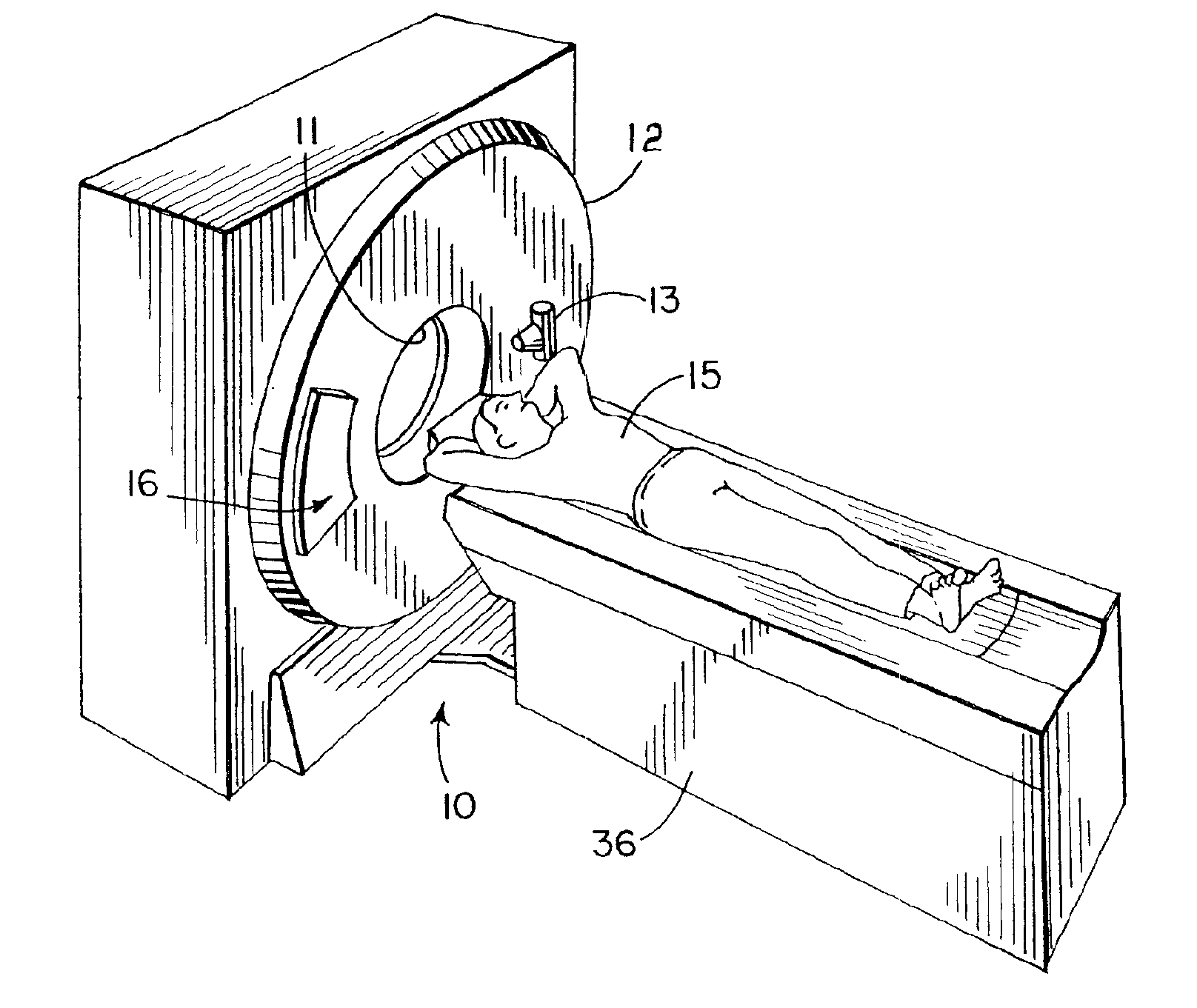
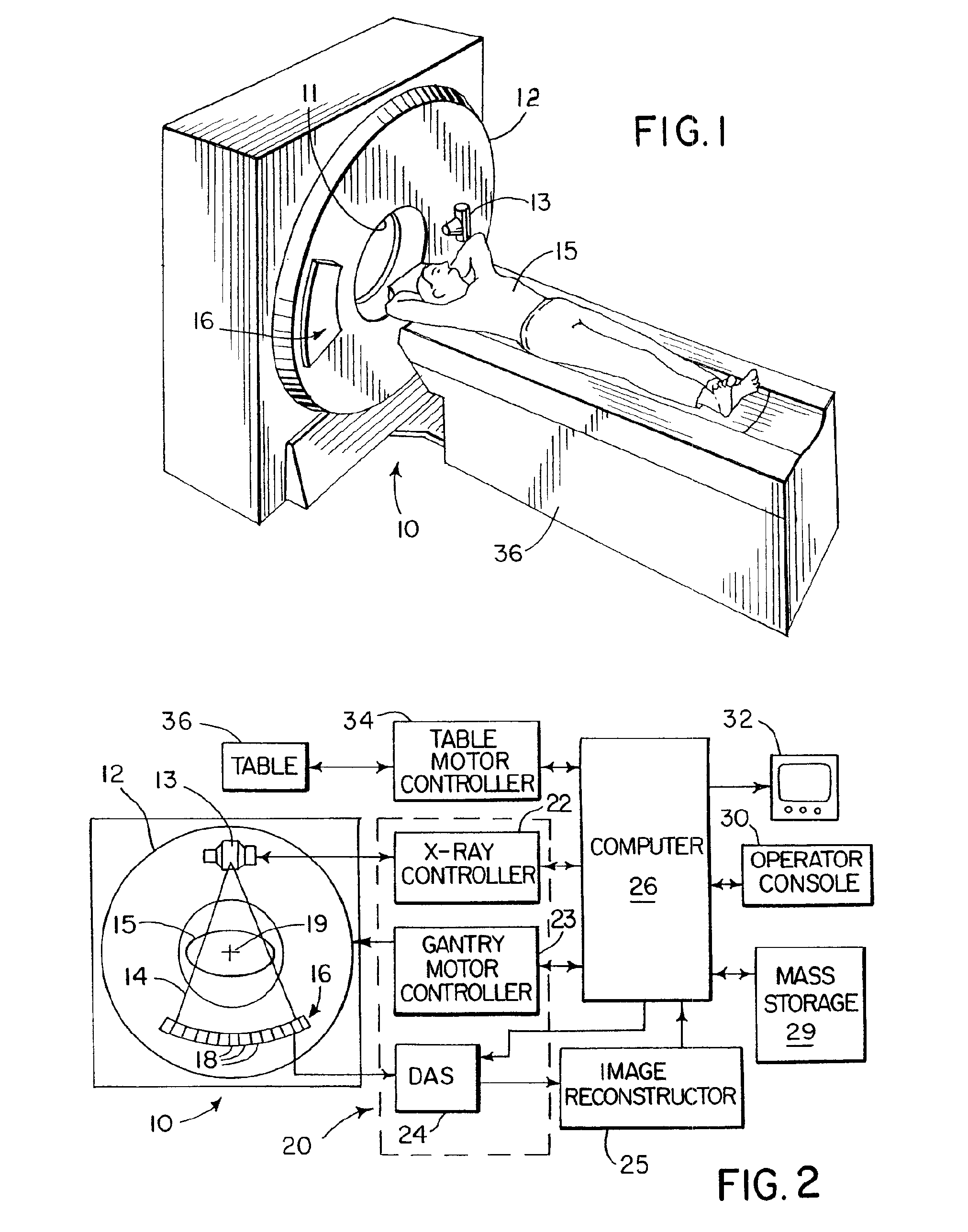
[0020]With initial reference to FIGS. 1 and 2, a computed tomography (CT) imaging system 10 includes a gantry 12 representative of a “third generation” CT scanner. Gantry 12 has a pair of x-ray sources 13 that each project a fan beam or cone beam of x-rays 14 toward a detector array 16 on the opposite side of the gantry. The detector array 16 is formed by a number of detector elements 18 which together sense the projected x-rays that pass through a medical patient 15. Each detector element 18 produces an electrical signal that represents the intensity of an impinging x-ray beam and hence the attenuation of the beam as it passes through the patient. During a scan to acquire x-ray projection data, the gantry 12 and the components mounted thereon rotate about a center of rotation 19 located within the patient 15 to acquire attenuation data for each of the two x-ray sources.

[0021]The rotation of the gantry and the operation of the x-ray sources 13 are governed by a control mechanism 20 ...


PUM


Abstract

Contrast from dual energy CT images is removed without affecting other aspects of the image, including objects surrounded by contrast. Dual energy images are acquired during a study of a subject. First, a binary mask image (“Contrast localizer”) is produced to localize the contrast-enhanced areas and build sets of images with contrast-enhanced areas only (“Contrast images”) and complement images with contrast-enhanced areas removed (“Contrast complement images”) for both low and high x-ray beam energy image sets. Only the contrast images are used for dual energy contrast subtraction. Second binary mask image (“Subject localizer”) is produced to localize the objects under study. This mask image is used to reconstruct both low and high energy image sets with contrast selectively removed and subject present.

Description

CROSS-REFERENCE TO RELATED APPLICATIONS[0001]This application claims priority to PCT International Application No. PCT / US2008 / 069933 filed on Jul. 14, 2008, which claims priority to U.S. Provisional Patent Application No. 60 / 949,626 filed on Jul. 13, 2007, which is hereby incorporated by reference herein in its entirety.BACKGROUND OF THE INVENTION[0002]The present invention relates to computed tomography (CT) imaging apparatus; and more particularly, contrast-enhanced images acquired at more than one x-ray energy level.[0003]In a current computed tomography system, an x-ray source projects a fan-shaped beam which is collimated to lie within an X-Y plane of a Cartesian coordinate system, termed the “imaging plane.” The x-ray beam passes through the object being imaged, such as a medical patient, and impinges upon an array of radiation detectors. The intensity of the transmitted radiation is dependent upon the attenuation of the x-ray beam by the object and each detector produces a se...

Claims


Application Information

Patent Timeline
Patent Type & Authority Patents(United States)
IPC IPC(8): G06K9/00A61B6/03A61B6/00G06T5/50A61B5/20
CPCA61B6/032A61B6/405A61B6/482G06T5/50A61B5/201A61B6/481G06T2207/10081
Inventor DZYUBAK, OLEKSANDR P.PRIMAK, ANDREW N.MCCOLLOUGH, CYNTHIA H.
Owner MAYO FOUND FOR MEDICAL EDUCATION & RES
Learn More