Conveyor chain, in particular a can conveyor chain

a conveyor chain and conveyor technology, applied in the field of conveyor chains, can solve the problems of narrowing the wall thickness in the specified direction, high noise emission, and corresponding impact noise, and achieve the effect of less failure prone and good damping characteristics

Active Publication Date: 2017-01-03
IWIS ANTRIEBSSYST
View PDF14 Cites 2 Cited by
  • Summary
  • Abstract
  • Description
  • Claims
  • Application Information

AI Technical Summary

Benefits of technology

[0004]Hence, it is the object of the present invention to provide a conveyor chain of the above specified type, which has good damping characteristics and which is less failure prone.
[0010]According to another embodiment, the annular bead and / or the spring section may have an opening so as to form the at least one air vent. Depending on the design of the opening, said opening may influence not only venting but it may also directly influence the spring behavior of the damping head. Hence, the term “annular” also comprises an interrupted contact area or bead, whose separated regions jointly extend circumferentially around a common center. Also very soft damping characteristics can be achieved in this way.
[0011]According to a particularly simple version of the damping head, said damping head is produced as an integral component. Hence, the individual areas may preferably be connected to one another by a substance to substance bond. Although it will be advantageous to produce the damping head of the same material in a uniform manner, it is also possible to connect different materials by a substance to substance bond (e.g. through co-injection molding).

Problems solved by technology

The cans are often shot onto the transport bars by means of compressed air, a circumstance which has hitherto entailed high noise emission.
The hitherto used hard plastics and the inertia of the spring systems resulted in a correspondingly audible impact noise.
In the case of many embodiments this results inevitably in a narrowing of the wall thickness in the specified direction.

Method used


Image

  • Conveyor chain, in particular a can conveyor chain
  • Conveyor chain, in particular a can conveyor chain
  • Conveyor chain, in particular a can conveyor chain

Examples


Embodiment Construction

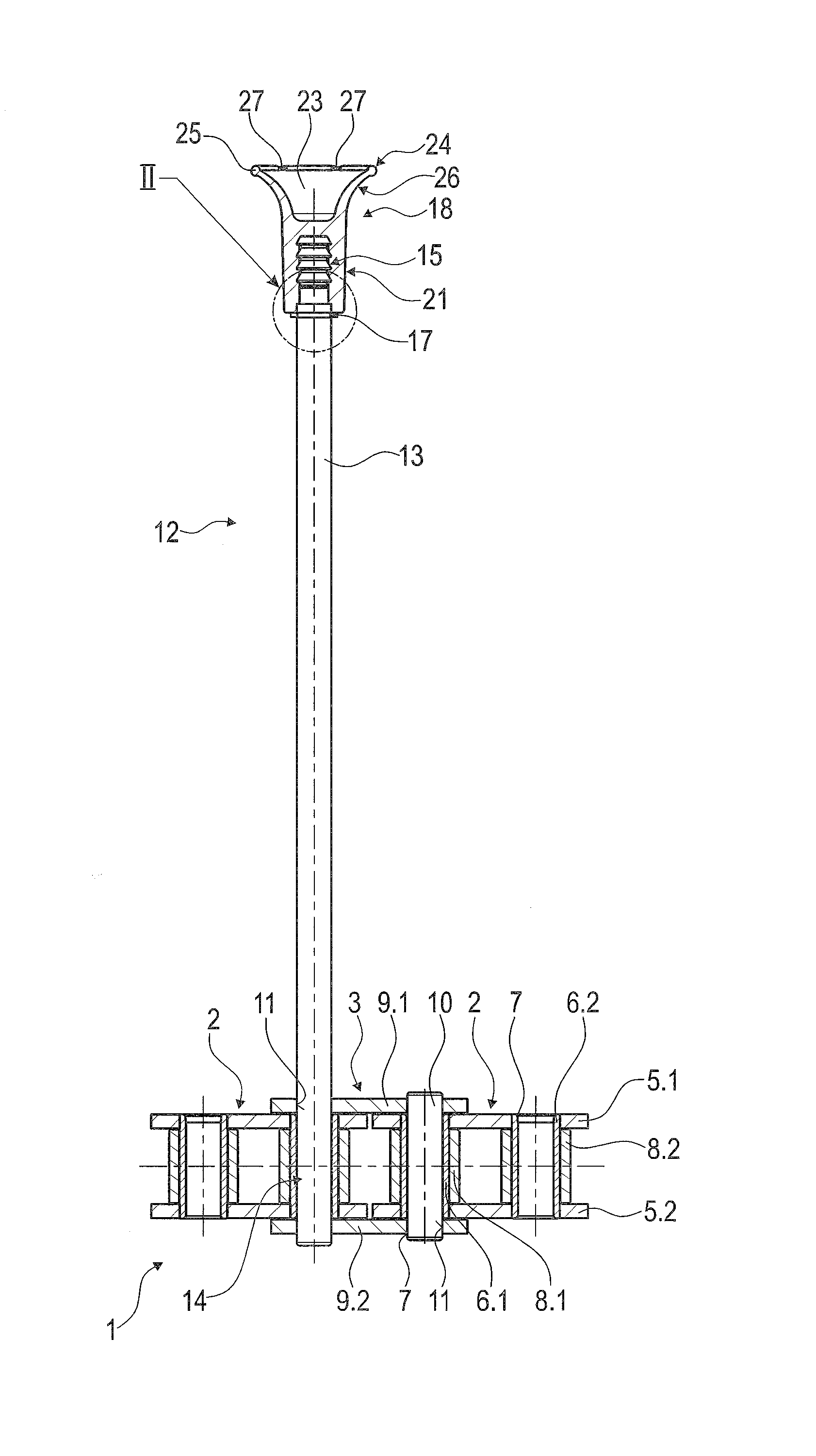
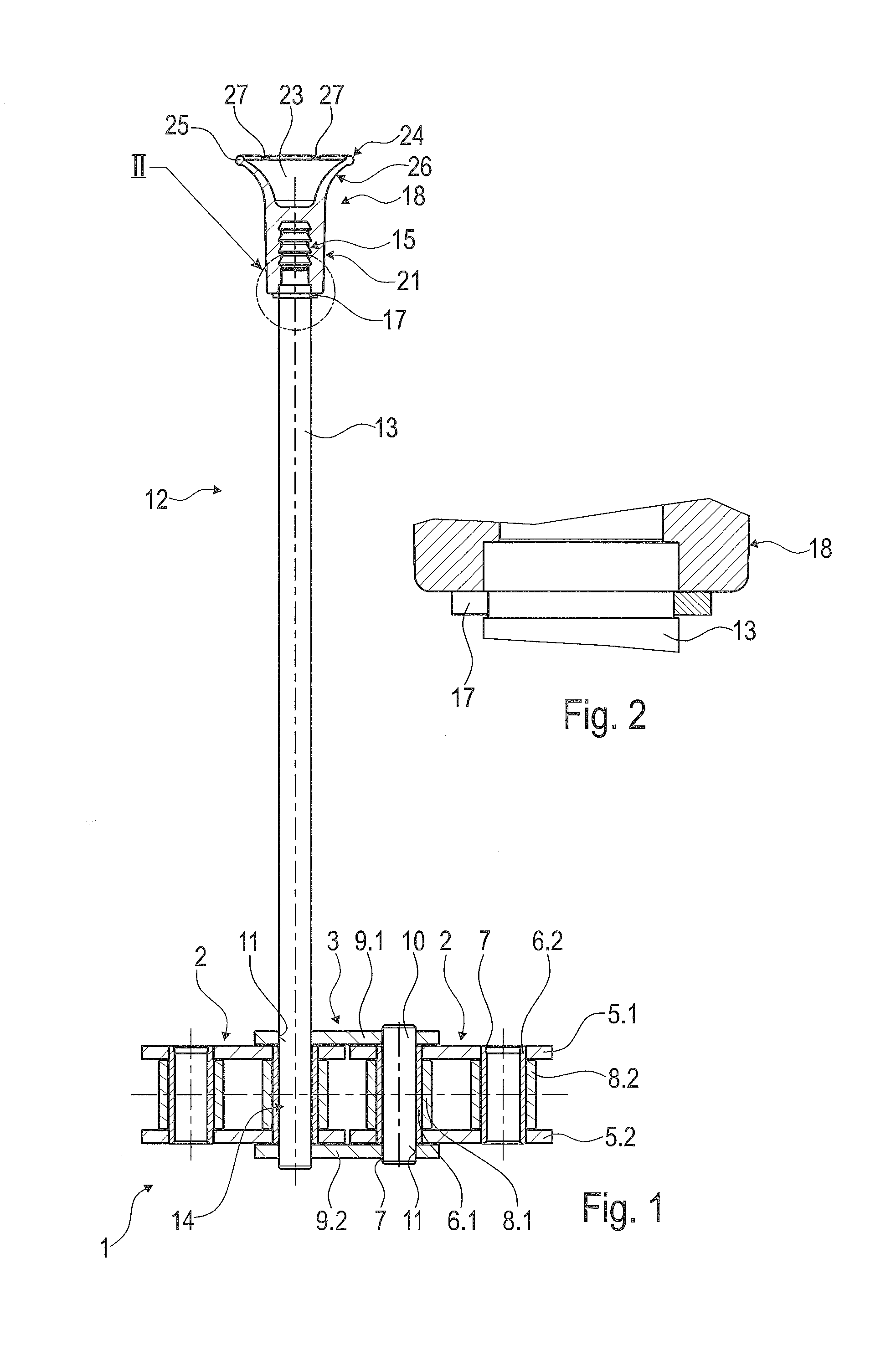
[0026]The conveyor chain 1 shown sectionwise in FIG. 1 is a can conveyor chain, which serves especially for conveying cans, in particular beverage cans, and which conveys the cans e.g. through a drying oven. In the course of this process, the conveyor chain is subject to elevated temperatures as well as paints and the resultant contamination. The highly delicate articles to be conveyed must not be damaged, and the damping characteristics of the conveyor chain 1 are therefore extremely important.

[0027]The conveyor chain 1 comprises alternating inner chain links 2 and outer chain links 3, which are connected to one another by means of a respective chain hinge 4. The inner chain link 2 comprises two spaced apart inner link plates 5.1 and 5.2, which are connected to one another by means of bushes 6.1 and 6.2 that also arranged in spaced relationship with one another. To this end, the inner link plates 5.1 and 5.2 are provided with suitable openings 7.1 and 7.2 having press-fitted therei...


PUM


Abstract

A conveyor chain, in particular a can conveyor chain, comprises chain links, which are interconnected by a respective chain hinge, and laterally projecting transport bars, which have a damping head made of a plastic material and provided for contact with the articles to be conveyed, the damping head comprising a fastening portion, a spring section arranged on said fastening portion and a contact portion connected to the spring section and adapted to contact the articles to be conveyed. A conveyor chain is provided of this type with a simpler and less failure-prone structural design. To this end, the damping head is provided with a front-side cavity of such a nature that the spring section has an elastically deformable wall portion whose wall thickness narrows, at least sectionwise, towards the contact portion, at least said spring section being made of an elastomer having a maximum shore hardness of A90.

Description

CROSS-REFERENCE TO RELATED APPLICATION[0001]This application claims priority to foreign German patent application No. DE 102014008925.8, filed on Jun. 17, 2014, the disclosure of which is incorporated by reference in its entirety.FIELD OF THE INVENTION[0002]The present invention relates to a conveyor chain, in particular a can conveyor chain, comprising chain links, which are interconnected by means of a respective chain hinge, and laterally projecting transport bars, which have a damping head made of a plastic material and provided for contact with the articles to be conveyed, said damping head comprising a fastening portion, a spring section arranged on said fastening portion and a contact portion connected to the spring section and adapted to contact the articles to be conveyed.BACKGROUND[0003]A conveyor chain of this type is known from DE 199 45 912 A1. The damping head is, at a lower portion thereof, fixedly connected to the upper end portion of a metal shaft of the transport b...

Claims


Application Information

Patent Timeline
Patent Type & Authority Patents(United States)
IPC IPC(8): B65G17/42B65G17/46B65G17/12B65G17/32
CPCB65G17/32B65G17/12B65G17/42B65G17/46B65G2201/0252B65G2207/38B65G17/40
Inventor TEUBER, TORALFMADLENER, FLORIAN
Owner IWIS ANTRIEBSSYST
Why Eureka
Try Eureka