Appliance for drying laundry

a technology for drying clothes and laundry, applied in the direction of other washing machines, washing apparatus, textiles and paper, etc., can solve the problems of agitation (tumbling) of the items to be dried, unsatisfactory, and disclosed solutions, and achieve the effect of facilitating the handling and mounting of heat exchangers, facilitating the handling of single bodies, and reducing the thickness

Active Publication Date: 2017-01-03
ELECTROLUX HOME PROD CORP NV
View PDF27 Cites 29 Cited by
  • Summary
  • Abstract
  • Description
  • Claims
  • Application Information

AI Technical Summary

Benefits of technology

[0017]Thus, in a preferred embodiment of the present invention, a drying air temperature sensor is located in the drying air recirculation path, downstream the Joule-effect drying air heater, preferably substantially at the entrance into the laundry treatment chamber and is coupled to the control unit to provide thereto measures about the temperature of the drying air entering into the laundry treatment chamber. The control unit is adapted to compare the measures of the drying air temperature with at least one predetermined temperature threshold (which may also depend on the specific laundry treatment cycle selected by the user via the cycle selector) and to automatically de-energize the Joule-effect drying air heater when the temperature threshold is reached.
[0033]According to another aspect of the present invention, there is provided a method of drying laundry in a laundry drying appliance comprising a cabinet, a laundry treatment chamber inside the cabinet, a drying air recirculation path for causing recirculation of the drying air into / out from the laundry treatment chamber, the drying air recirculation path being at least partly external to the laundry treatment chamber, a drying air moisture condensing and heating system located in the drying air recirculation path for dehydrating the drying air leaving the laundry treatment chamber and heating the dehydrated drying air before it re-enters into the laundry treatment chamber, wherein said drying air moisture condensing and heating system comprises a first heat exchanger and a second heat exchanger of a heat pump, and further comprising drying air propeller inside the drying air recirculation path and a Joule-effect drying air heater, downstream the second heat exchanger, energizable for contributing to the heating of the drying air.
[0067]Said first and second heat exchangers are assembled to form a single body by means of at least one joining member mounted to the first and second heat exchangers on at least one side thereof and provided with holes for the passage of the piping, wherein in the resulting single body the first and second heat exchangers are aligned one to the other and the respective packs of heat-exchange fins are spaced apart by a gap along a direction of flow of the heat pump process fluid. This facilitates the handling and mounting of the heat pump heat exchangers.
[0068]The at least one joining member may be made in a same material as the heat-exchange fins but having a greater thickness, and / or the joining member may be made in a material different from the material of the heat-exchange fins, to be more resistant. This facilitates the handling of the single body and prevents damaging of the packs of heat-exchange fins.
[0069]Preferably, a positioning member is provided in the at least one joining member, adapted to enable a correct and easy positioning and centering of the single body in an intended seat.
[0073]In this way, it is prevented that any fluff transported by the drying air may enter the washing liquid dispensing system of the machine.

Problems solved by technology

The rotation of the drum causes agitation (tumbling) of the items to be dried, while they are hit by the drying air flow.
The Applicant believes that the solution disclosed in DE 4304226 is not fully satisfactory.
Systematically activating the resistance heating is not believed to be a good idea: there may be cases in which the additional heating action of the resistance heating is not necessary, the heating action of the heat pump being sufficient; this thus leads to unnecessary electric energy consumption.
Another problem that, according to the Applicant, affects the solution of DE 4304226 is that the electronic program control decides whether to switch off or on the resistance heating when the pressure of the cooling agent (in the heat pump) exceeds a critical value (and this condition is inferred from the measure of the temperature of the connecting tube between the heat pump compressor and liquefier, proportional to the pressure of the cooling agent).
DE 4304226 is indeed concerned about the possible occurrence of impermissibly high temperatures in the liquefier of the heat exchanger as a result of the additional heating, because such an increase in the temperature can lead to the destruction of the entire heat pump system.
The Applicant observes that controlling the switching on / off of the resistance heating based on the detected temperature of the connecting tube between the heat pump compressor and liquefier is so slow a control, that the control of the drying air temperature cannot be timely, nor reliable.
DE 4304226 however completely neglects the possible detrimental effect that the additional heating may have on the laundry items being dried.

Method used


Image

  • Appliance for drying laundry
  • Appliance for drying laundry
  • Appliance for drying laundry

Examples


Embodiment Construction

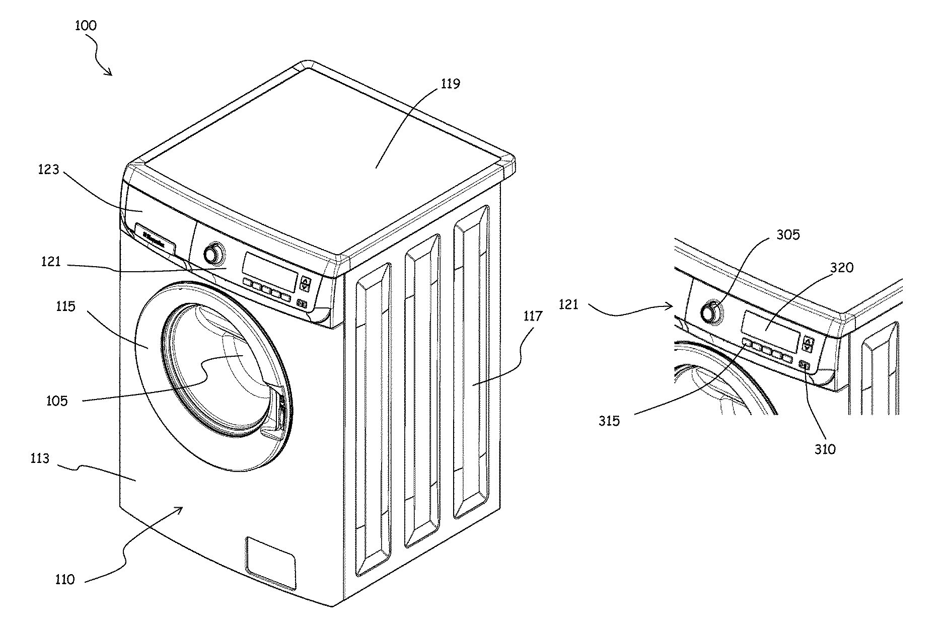
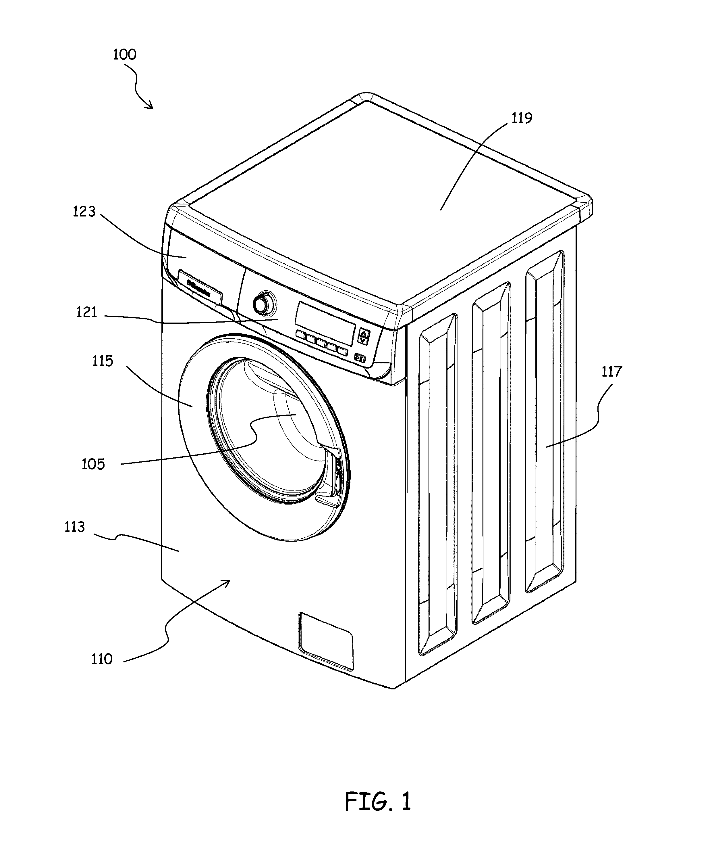
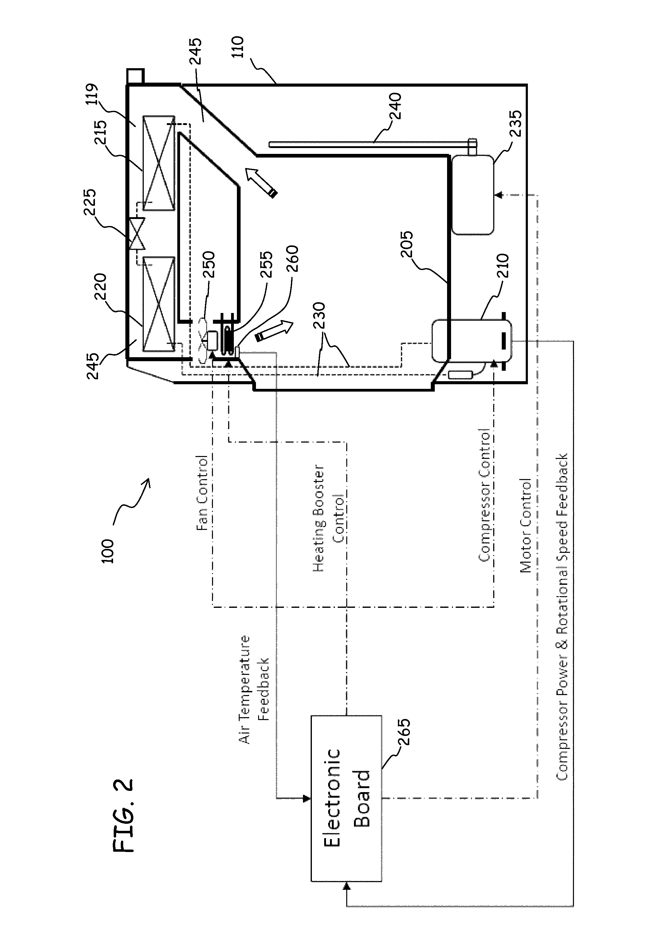
[0084]With reference to the drawings, a laundry drying appliance, for example a laundry washer / dryer, according to an embodiment of the present invention is depicted in FIG. 1 in perspective from the front. The laundry dryer, globally denoted as 100, comprises a laundry treatment chamber 105 for accommodating the items to be washed and / or dried such as clothes, garments, linen, and similar laundry item. Preferably the laundry treatment chamber 105 includes a drum rotatably mounted inside the machine casing or cabinet 110, and in case of a dryer with washing functionality (i.e., a laundry washer / dryer) the drum is arranged within a tub housed in the machine casing or cabinet 110.

[0085]The cabinet 110 is generically a parallelepiped in shape, and has a front wall 113, two side walls 117, a rear wall, a basement and a top 119. The front wall 113 is provided with an opening for accessing the laundry treatment chamber 105 and with an associated door 115 for closing the opening. In the up...


PUM


Abstract

An appliance for drying laundry (100) comprises an appliance cabinet (110), a laundry treatment chamber (105) inside the cabinet, and a drying air recirculation path (245) for causing recirculation of the drying air into / out from the laundry treatment chamber. The drying air recirculation path is at least partly external to the laundry treatment chamber. A drying air moisture condensing and heating system (215,220,225) located in the drying air recirculation path for dehydrating the moisture-laden drying air leaving the laundry treatment chamber and heating the dehydrated drying air before it re-enters into the laundry treatment chamber. The drying air moisture condensing and heating system comprises a first heat exchanger (215) and a second heat exchanger (220) of a heat pump (215,220,225,210), and further comprising a drying air propeller (250) inside the drying air recirculation path and a Joule-effect drying air heater (255), downstream the second heat exchanger, energizable for contributing to the heating of the drying air. The appliance includes a user interface (121) comprising a laundry treatment cycle selector (305) operable by a user for selecting a laundry treatment cycle, and a control unit (265) adapted to control the machine operation. The user interface comprises a command input means (315) operable by the user for imparting to the appliance an energization command to energize the Joule-effect heater. During the execution of the laundry treatment cycle selected by the user, the control unit causes the selective energization of the Joule-effect drying air heater based on the energization command imparted by the user.

Description

BACKGROUND OF THE INVENTION[0001]Field of the Invention[0002]The present invention generally relates to the field of household appliances for laundry and garments treatment. In particular, the present invention relates to appliances for drying laundry, such as laundry dryers and combined washers / dryers.[0003]Discussion of the Related Art[0004]Appliances for drying laundry are adapted to dry clothes, garments, laundry in general, by circulating hot, dry air within a tumbler or drum. The drum is rotatable within a machine external casing or cabinet, and is designed to contain the items to be dried. The rotation of the drum causes agitation (tumbling) of the items to be dried, while they are hit by the drying air flow.[0005]Combined laundry washer / dryer appliances combine the features of a washing machine with those of a dryer. In a washer / dryer, the drum is rotatable within a washing tub which is accommodated within a machine external casing or cabinet.[0006]In a known type of laundry...

Claims


Application Information

Patent Timeline
Patent Type & Authority Patents(United States)
IPC IPC(8): D06F58/20D06F58/24D06F39/02D06F29/00D06F58/28D06F25/00
CPCD06F29/005D06F25/00D06F39/02D06F58/206D06F58/24D06F58/28D06F2058/289D06F58/20D06F58/38D06F2101/20D06F2103/32D06F2105/28
Inventor CONTARINI, ANDREAVIERO, MASSIMO
Owner ELECTROLUX HOME PROD CORP NV
Why Eureka
Try Eureka