System and method for providing traffic congestion relief using dynamic lighted road lane markings

a technology of dynamic light and road lane marking, which is applied in the field of system and method for providing traffic congestion relief, can solve the problems of slow commuting travel, road functions in a much less efficient manner, and the geometrics cannot change or adapt, so as to increase the traffic carrying capacity of the road, reduce traffic congestion, and increase driving safety

Active Publication Date: 2017-01-03
SOLTESZ JAMES A
View PDF16 Cites 41 Cited by
  • Summary
  • Abstract
  • Description
  • Claims
  • Application Information

AI Technical Summary

Benefits of technology

[0010]One aspect of the present invention provides a system and method for providing increased traffic carrying capacity of a road, such as a highway. The system and method operates to reduce traffic congestion and increase driving safety by modifying an existing roadway from, for example, four lanes to five lanes to create an additional travel lane. In particular, the system and method dynamically changes the widths and number of travel lanes using dynamic indicators, such as LED embedded pavement lights in the road surface or other types of lighting arrangements, in lieu of traditional painted lane lines. The system and method utilize, for example, functionality of an intelligent transportation system (ITS). As traffic volumes increase and speeds decrease along the road, the ITS sends a signal, such as a wirel

Problems solved by technology

Because these geometrics are static, the geometrics cannot change or adapt regardless of the real time operations of traffic on a road.
However, at other times when the designed vehicle travel speeds are not achievable due to, for example, congestion caused by over capacity of the traditional road design parameters, the road functions in a much less efficient manner.
Hence, traffic jams, congestion, slower commuting travel, increased air pollution due to stop and go traffic, traffic speeds less than the designed vehicle travel speeds, and other undesirable circumstances occur.
Typically, neith

Method used


Image

  • System and method for providing traffic congestion relief using dynamic lighted road lane markings
  • System and method for providing traffic congestion relief using dynamic lighted road lane markings
  • System and method for providing traffic congestion relief using dynamic lighted road lane markings

Examples


Embodiment Construction

[0023]Selected embodiments will now be explained with reference to the drawings. It will be apparent to those skilled in the art from this disclosure that the following descriptions of the disclosed embodiments are provided for illustration only and not for the purpose of limiting the invention as defined by the appended claims and their equivalents.

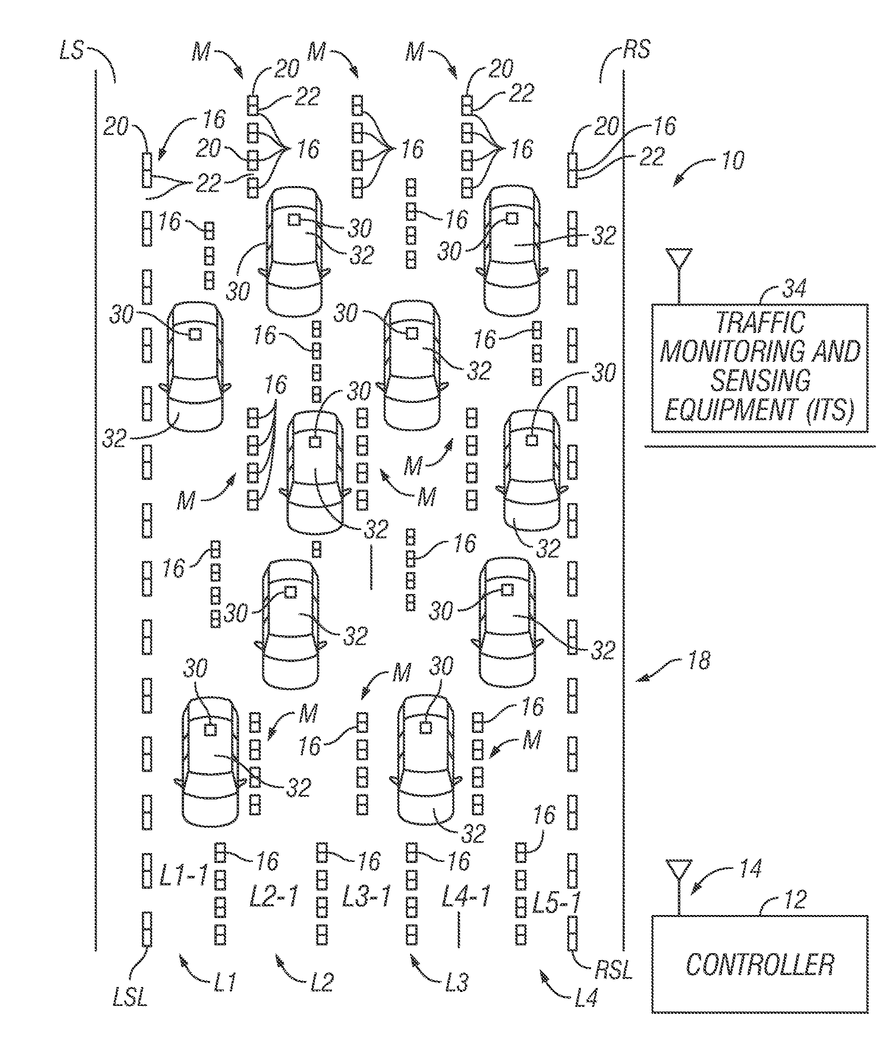
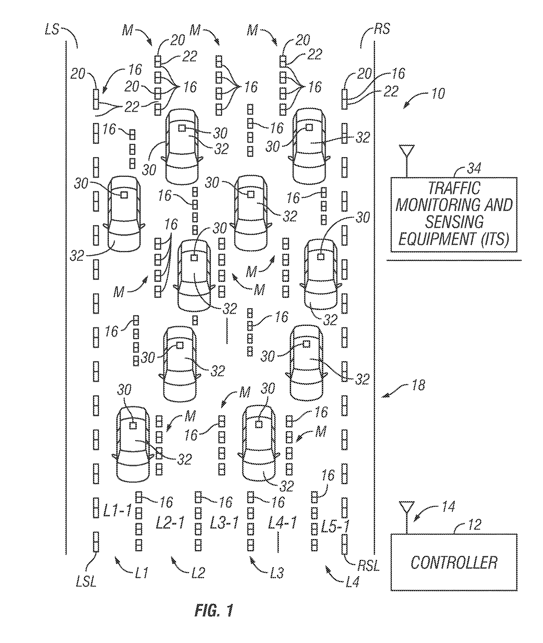
[0024]FIG. 1 illustrates an example of a system and method for providing traffic congestion relief 10 (known as “SmartRoad”) according to a disclosed embodiment. As shown, the system 10 includes one or more controllers 12. Each controller 12 includes at least one communication device 14, such as a wireless communication device or wired communication device, for communicating information to and from external sources. For example, the communication device 14 enables the controller 12 to communicate with dynamic indicators 16 associated with a road segment 18, such as a portion of a highway or any type of road that permits vehicular traffic...


PUM


Abstract

A system and method for providing increased traffic carrying capacity of a road, such as a highway, by modifying an existing roadway from, for example, four lanes to five lanes, to create an additional travel lane. The system and method dynamically changes the width of travel lanes using, for example, embedded pavement lights, or other lighting arrangements, in lieu of traditional painted lane lines. As traffic volumes increase and speeds decrease along the road, an intelligent transport system (ITS) sends a congestion signal to the overhead lane controls and dynamic message signs (DMS) along the entire road segment of interest. The posted speed limits are changed, and the lane markings are controlled to dynamically increase the number of lanes in the road segment to five, for example, of narrower widths until traffic volumes reduce and the number of lanes can be returned to four, for example, with normal speed limits.

Description

CROSS-REFERENCE TO RELATED APPLICATION[0001]This application is a continuation-in-part of U.S. patent application Ser. No. 15 / 094,446, filed on Apr. 8, 2016, now U.S. Pat. No. 9,460,618, which claims priority to U.S. Provisional Patent Application No. 62 / 297,708, filed on Feb. 19, 2016, the entire contents of U.S. patent application Ser. No. 15 / 094,446 and U.S. Provisional Patent Application No. 62 / 297,708 being incorporated by reference herein.BACKGROUND[0002]Field of the Invention[0003]The present invention generally relates to a system and method for providing traffic congestion relief. More particularly, the present invention relates to a system and method for providing traffic congestion relief by receiving data from traffic and speed sensing monitors and, based on that data, operating a lighted lane markings, such as LED in-pavement lane markings, to change the widths and number of the traffic lanes, thus maximizing the number of lanes based on congestion and speed of the vehi...

Claims


Application Information

Patent Timeline
IPC IPC(8): G08G1/095G08G1/01G08G1/08
CPCG08G1/0145G08G1/08G08G1/0116G08G1/0133G08G1/052G08G1/096716G08G1/09675G08G1/096783E01F9/582
Inventor SOLTESZ, JAMES AGUCKERT, JOHN WES
Owner SOLTESZ JAMES A
Why Eureka
Try Eureka