Method and device for determining the optimal turn direction of an aircraft

a technology of optimal turn direction and aircraft, applied in the field of method and device for determining the optimal turn direction of aircraft, can solve the problems of incompatibility of computation mode and insatiable computation trajectory

Active Publication Date: 2017-01-03
THALES SA
View PDF30 Cites 4 Cited by
  • Summary
  • Abstract
  • Description
  • Claims
  • Application Information

AI Technical Summary

Problems solved by technology

This mode of computation thus presents the drawback of not corresponding, for certain geometries, to the natural direction that would be chosen by the pilot or to the direction minimizing the distance travelled by the aircraft to join the straight Da.
This computed trajectory is not satisfactory since it is not slaved sufficiently to the flight plan and hinders the pilots as well as the air traffic control.

Method used


Image

  • Method and device for determining the optimal turn direction of an aircraft
  • Method and device for determining the optimal turn direction of an aircraft
  • Method and device for determining the optimal turn direction of an aircraft

Examples


first embodiment

[0104] illustrated in FIG. 8A, the sub-step 320 of determining the sign of the optimal turn STDopt when the signs are equal, consists in assigning the opposite of the logical sign SI to the sign of the optimal turn STDopt.

[0105]This entails a first choice of very simple logic.

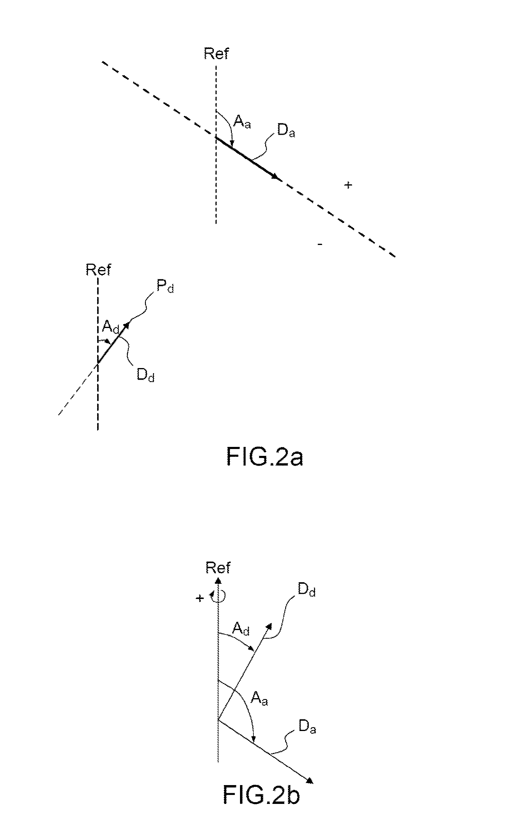
[0106]FIG. 8B illustrates this situation with an exemplary flight geometry in respect of an aircraft flying a flight plan comprising the legs. The FMS system seeks to compute a lateral trajectory from the first leg L1 corresponding to the position Pd according to a course Ad, to the following leg or second leg L2 exhibiting a course Aa according to the arrival straight Da.

[0107]The logical sign SI is negative since the value of TCc is negative.

[0108]A system according to the prior art computes a joining trajectory 80 comprising a leftward turn direction LTD.

[0109]The sign of the point Pd is negative, and therefore the sign of Pd SPd and the logical sign are both negative. The method 10 according to the inventio...

second embodiment

[0110] illustrated in FIG. 9, the sub-step 320 of determining the sign of the optimal turn STDopt when the signs are equal is performed as a function of the absolute value of the centred value of the angle of change of course TCc and / or of the distance Dist between the departure point Pd and the arrival straight Da.

[0111]The introduction of two criteria, one dependent on ITCcI and the other on Dist, these criteria being able to be used independently or cumulatively, makes it possible to refine the logic for determining TDopt.

[0112]FIG. 10 describes a first variant of the second embodiment.

[0113]According to this variant, the sub-step 320 of determining the sign of the optimal turn STDopt when the signs are equal comprises a sub-step 321 which compares the absolute value of the centred value of the angle of change of course ITCcI with an angle equal to 180° minus a joining angle AR lying between 10° and 90°.

[0114]A joining angle AR corresponds to the angle according to which an aircr...


PUM


Abstract

A method determines the optimal turn direction of an aircraft among two directions, right and left, following a lateral trajectory to join an arrival straight charted by an angle of arrival, based on a departure point and angle of departure defining a departure straight oriented along movement of the aircraft, the direction defined by a respectively positive or negative optimal turn sign, comprising: determining a conventional departure sign of the departure point; determining a center value of an angle of change of course equal to the difference between the angle of arrival and angle of departure referred back between −180° and +180°, the center value exhibiting a logical sign corresponding to the center value sign of the angle of change of course; determining the sign of the optimal turn based on comparison between the departure sign and the logical sign, the sign of the optimal turn defining optimal turn direction.

Description

CROSS-REFERENCE TO RELATED APPLICATION[0001]This application claims priority to foreign French patent application No. FR 1401300, filed on Jun. 6, 2014, the disclosure of which is incorporated by reference in its entirety.FIELD OF THE INVENTION[0002]The present invention relates to a method for computing continuous geometric lateral trajectories between a departure point and an arrival straight. It applies notably to the field of avionics, and more particularly to the flight management devices customarily referred to by the acronym FMS standing for the expression “Flight Management System”.BACKGROUND[0003]Most current aircraft possess a flight management system, for example of the FMS type, the acronym standing for the term “Flight Management System”. These systems allow navigational aid, by displaying information useful to pilots, or else by communicating flight parameters to an automatic piloting system.[0004]Notably, a system of FMS type allows a pilot or another qualified person...

Claims


Application Information

Patent Timeline
Patent Type & Authority Patents(United States)
IPC IPC(8): G08G5/00G05D1/02
CPCG08G5/0034G05D1/0202G08G5/0039G08G5/0047
Inventor SAVARIT, VINCENTHOOFD, FRANCOISDEWAS, EMMANUEL
Owner THALES SA
Why Eureka
Try Eureka