Information signal representation using lapped transform

a technology of information signal and transform, applied in the direction of speech analysis, sound producing devices, ear treatment, etc., to achieve the effect of high coding efficiency, efficient use of lapped transform representation, and efficient traversal

Active Publication Date: 2017-01-03
FRAUNHOFER GESELLSCHAFT ZUR FOERDERUNG DER ANGEWANDTEN FORSCHUNG EV
View PDF287 Cites 0 Cited by
  • Summary
  • Abstract
  • Description
  • Claims
  • Application Information

AI Technical Summary

Benefits of technology

[0012]The main thoughts which lead to the present invention are the following. Lapped transform representations of information signals are often used in order to form a pre-state in efficiently coding the information signal in terms of, for example, rate / distortion ratio sense. Examples of such codecs are AAC or TCX or the like. Lapped transform representations may, however, also be used to perform re-sampling by concatenating transform and re-transform with different spectral resolutions. Generally, lapped transform representations causing aliasing at the overlapping portions of the individual retransforms of the transforms of the windowed versions of consecutive time regions of the information signal have an advantage in terms of the lower number of transform coefficient levels to be coded so as to represent the lapped transform representation. In an extreme form, lapped transforms are “critically sampled”. That is, do not increase the number of coefficients in the lapped transform representation compared to the number of time sample of the information signal. An example of a lapped transform representation is an MDCT (Modified Discrete Cosine Transform) or QMF (Quadratur Mirror Filters) filterbank. Accordingly, it is often favorable to use such a lapped transform representations as a pre-state in efficiently coding information signals. However, it would also be favorable to be able to allow the sample rate at which the information signal is represented using the lapped transform representation to change in time so as to be adapted, for example, to the available transmission bitrate or other environmental conditions. Imagine a varying available transmission bitrate. Whenever the available transmission bitrate falls below some predetermined threshold, for example, it may be favorable to lower the sample rate, and when the available transmission rate raises again it would be favorable to be able to increase the sample rate at which the lapped transform representation represents the information signal. Unfortunately, the overlapping aliasing portions of the retransforms of the lapped transform representation seem to form a bar against such sample rate changes, which bar seems to be overcome only by completely interrupting the lapped transform representation at instances of sample rate changes. The inventors of the present invention, however, realized a solution to the above-outlined problem, thereby enabling an efficient use of lapped transform representations involving aliasing and the sample rate variation in concern. In particular, by interpolation, the preceding and / or succeeding region of the information signal is resampled at the aliasing cancellation portion according to the sample rate change at the border between both regions. A combiner is then able to perform the aliasing cancellation at the border between the retransforms for the preceding and succeeding regions as obtained by the resampling at the aliasing cancellation portion. By this measure, sampling rate changes are efficiently traversed with avoiding any discontinuity of the lapped transform representation at the sample rate changes / transitions. Similar measures are also feasible at the transform side so as to appropriately generate a lapped transform.
[0013]Using the idea just outlined, it is possible to provide information signal compression techniques, such as audio compression techniques, which have high coding efficiency over a wide range of environmental coding conditions such as available transmission bandwidth by adapting the conveyed sample rate to these conditions with no penalty by the sample rate change instances themselves.

Problems solved by technology

Unfortunately, the overlapping aliasing portions of the retransforms of the lapped transform representation seem to form a bar against such sample rate changes, which bar seems to be overcome only by completely interrupting the lapped transform representation at instances of sample rate changes.

Method used


Image

  • Information signal representation using lapped transform
  • Information signal representation using lapped transform
  • Information signal representation using lapped transform

Examples


Embodiment Construction

[0028]In order to motivate the embodiments of the present invention further described below, preliminarily, embodiments are discussed within which embodiments of the present application may be used, and which render the intention and the advantages of the embodiments of the present application outlined further below clear.

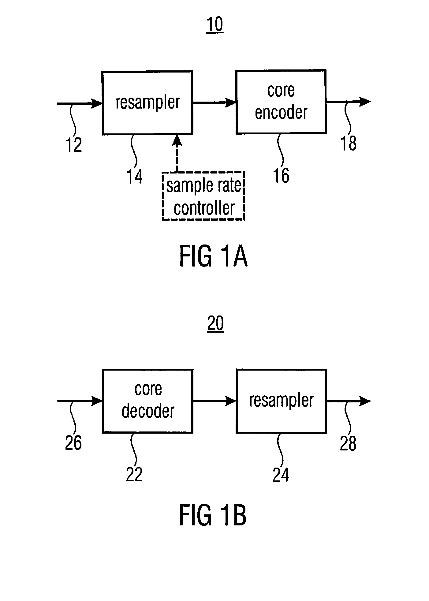
[0029]FIGS. 1a and 1b show, for example, a pair of an encoder and a decoder where the subsequently explained embodiments may be advantageously used. FIG. 1a shows the encoder while FIG. 1b shows the decoder. The information signal encoder 10 of FIG. 1a comprises an input 12 at which the information signal enters, a resampler 14 and a core encoder 16, wherein the resampler 14 and the core encoder 16 are serially connected between the input 12 and an output 18 of encoder 10. At the output 18 encoder 10 outputs the data stream representing the information signal of input 12. Likewise, the decoder shown in FIG. 1b with reference sign 20 comprises a core decoder 22 and ...


PUM


Abstract

An information signal reconstructor is configured to reconstruct, using aliasing cancellation, an information signal from a lapped transform representation of the information signal including, for each of consecutive, overlapping regions of the information signal, a transform of a windowed version of the respective region, wherein the information signal reconstructor is configured to reconstruct the information signal at a sample rate which changes at a border between a preceding region and a succeeding region of the information signal.

Description

CROSS-REFERENCE TO RELATED APPLICATIONS[0001]This application is a continuation of copending International Application No. PCT / EP2012 / 052458, filed Feb. 14, 2012, which is incorporated herein by reference in its entirety, and additionally claims priority from U.S. Patent Application No. 61 / 442,632, filed Feb. 14, 2011, which is also incorporated herein by reference in its entirety.BACKGROUND OF THE INVENTION[0002]The present application is concerned with information signal representation using lapped transforms and in particular the representation of an information signal using a lapped transform representation of the information signal necessitating aliasing cancellation such as used, for example, in audio compression techniques.[0003]Most compression techniques are designed for a specific type of information signal and specific transmission conditions of the compressed data stream such as maximum allowed delay and available transmission bitrate. For example, in audio compression, ...

Claims


Application Information

Patent Timeline
Patent Type & Authority Patents(United States)
IPC IPC(8): G10L19/00G10L19/012G10L25/78G10L21/0216G10L19/22G10L19/03G10K11/16G10L19/12G10L19/005G10L19/04G10L19/02G10L19/107G10L19/025G10L25/06G10L19/26
CPCG10L19/00G10K11/16G10L19/005G10L19/012G10L19/03G10L19/12G10L19/22G10L21/0216G10L25/78G10L19/025G10L19/0212G10L19/04G10L19/107G10L19/26G10L25/06G10L19/022G10L19/18G10L19/028G10L19/08G10L19/02G10L19/07G10L19/10G10L19/13
Inventor SCHNELL, MARKUSGEIGER, RALFRAVELLI, EMMANUELFOTOPOULOU, ELENI
Owner FRAUNHOFER GESELLSCHAFT ZUR FOERDERUNG DER ANGEWANDTEN FORSCHUNG EV
Why Eureka
Try Eureka