Press-type liquid pump

a liquid pump and press-type technology, which is applied in the direction of springs, single-unit apparatuses, spinning apparatuses, etc., can solve the problems of affecting the amount of liquid output of the liquid pump, the pump rusts easily, and the quality of the product is affected

Active Publication Date: 2017-01-10
DING YAOWU
View PDF34 Cites 22 Cited by
  • Summary
  • Abstract
  • Description
  • Claims
  • Application Information

AI Technical Summary

Benefits of technology

[0016]With the above-mentioned liquid pumps of the present invention, since an elastic restoring means made of a plastic is provided, the problems of difficult disassembly, difficult recovery, high cost and easy pollution of the environment of metal springs are solved; meanwhile, the use of the elastic restoring means in the form of an arc-shaped elastic strip solves the problems of high hand pressing force and insufficient rebounding force of existing plastic spring liquid pumps.
[0017]In addition, the elastic restoring means of the present invention is arranged at a position below the toothed sleeve, which position is hidden within the product container and not exposed in normal use, thus not only can the damage to the elastic restoring means due to an external collision be avoided, but also the aesthetics of a product container equipped with the liquid pump can be improved.

Problems solved by technology

However, keeping the elastic restoring means in a loaded state for a long time would result in creeping and fatigue failure of the elastic means, ultimately resulting in an insufficient rebounding force to restore the movable unit into position, and thereby influencing the amount of liquid outputted by the liquid pump.
The metal spring 1010 for use in this liquid pump rusts easily due to damp or contact with liquid, and a rusted spring affects the quality of the product (including the quality of the spring and the quality of the liquid product in the container).
Moreover, the cost of the metal spring is relatively high, and in the recycling of the liquid pump, the metal spring needs to be disassembled from other plastic members for separate recovery, which greatly increases the cost of recovery.
However, this bellows type plastic spring inherently presents the problem of an insufficient elastic force, which, in the case that the liquid product is relatively viscous or a relatively high amount of liquid to be pumped out is required, will inevitably make a rebound difficult or even impossible, thereby affecting the use by consumers.
Furthermore, in order to enable such a liquid pump to rebound into position during use, the bellows must be installed in a pre-loaded manner such that it has been subjected to a certain pre-stressed deformation before use; however, after it has been in place for a long time or due to changes in the ambient temperature, the bellows spring is prone to creeping, resulting in the previously stored elastic deformation disappearing, thereby resulting in a reduced rebounding force.
A disadvantage of the spring 1210 used in this liquid pump is that a very large downward pressing force is required to bend the spring when the pressing head is in the vicinity of an upper stop position of a pressing stroke, and the rebounding force that can be provided by this plastic spring is too small when the pressing head is in the vicinity of a lower stop position of the pressing stroke, resulting in a slow or incomplete restoration.
Moreover, in terms of the appearance, the casing type spring is arranged above the toothed sleeve of the liquid pump, making the section above the toothed sleeve particularly bulky and even larger after a downward pressing, which is very unattractive.

Method used


Image

  • Press-type liquid pump
  • Press-type liquid pump
  • Press-type liquid pump

Examples


embodiment 1

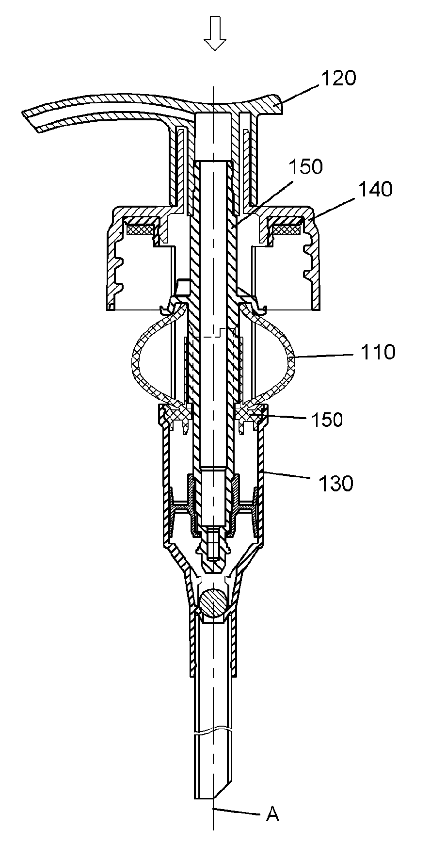
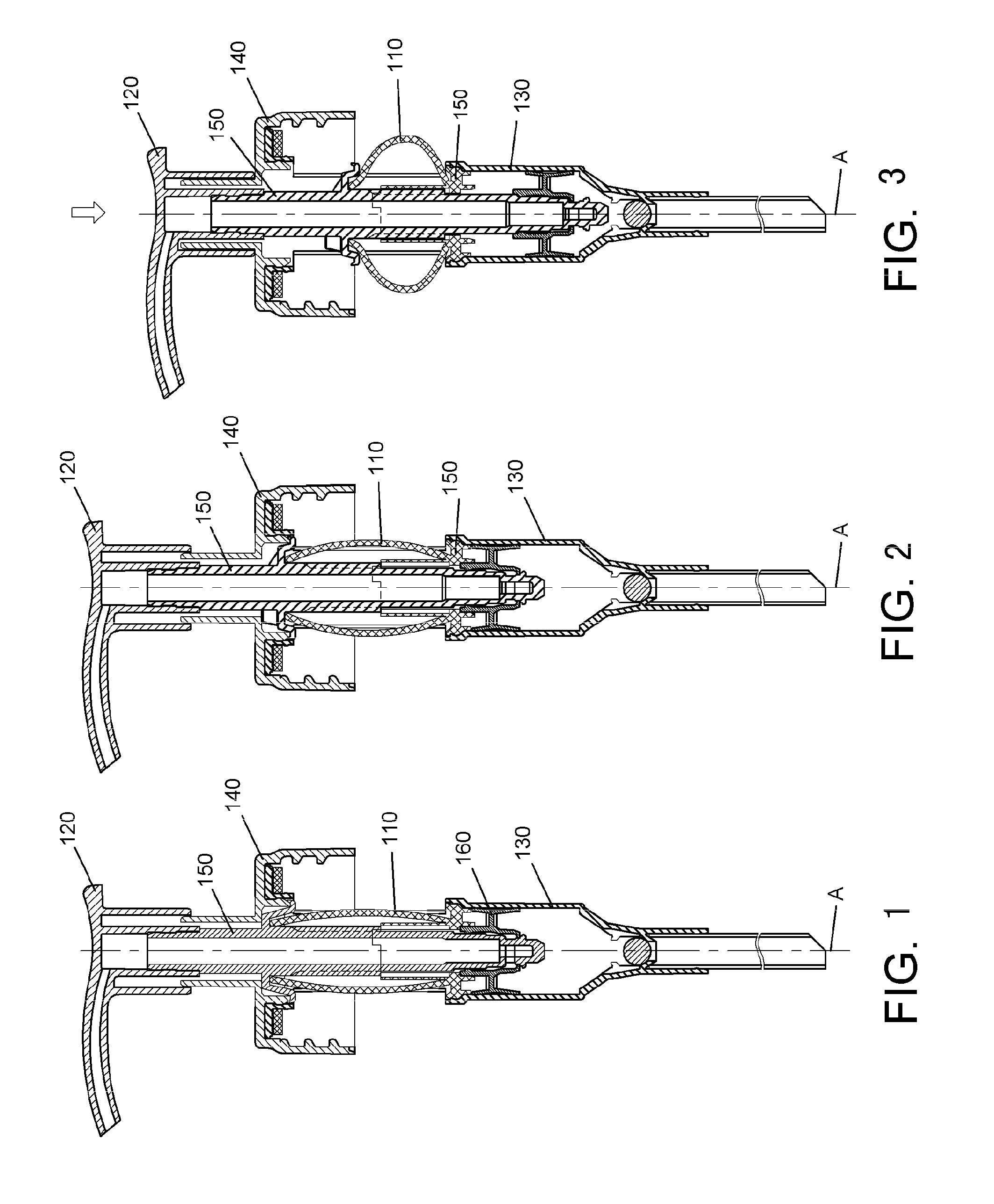
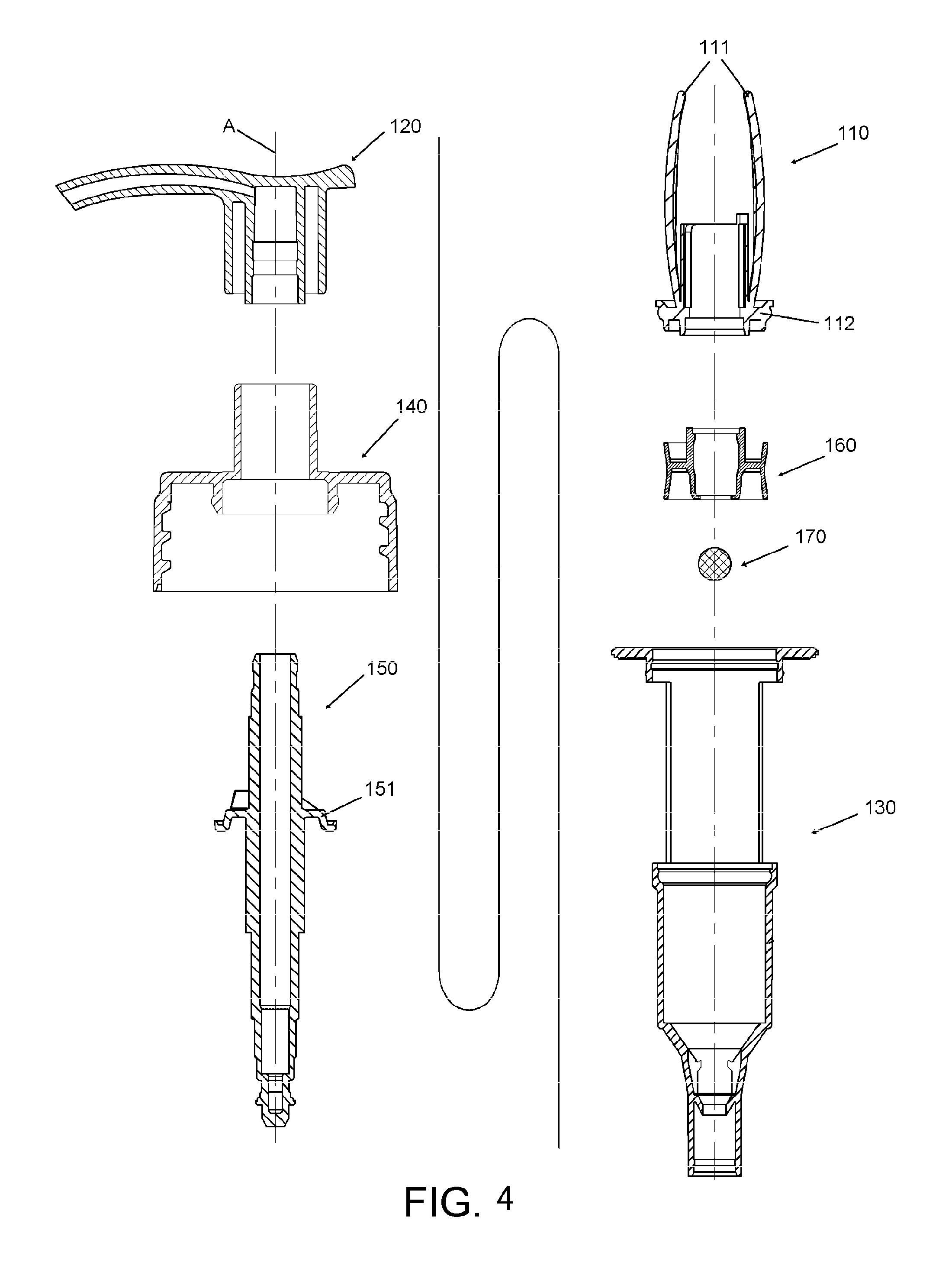
[0073]Reference is made to FIGS. 1-7, which show a press-type liquid pump according to a first embodiment of the present invention. The press-type liquid pump is fitted onto a container (not shown) to pump a liquid product within the container to the exterior of the container. In general, the liquid pump comprises a fixed unit fixed relative to the container and a movable unit capable of performing a reciprocating motion relative to the fixed unit, and the liquid product is pumped to the exterior of the container by means of the reciprocating motion. The reciprocating motion is achieved by a pressing force applied by a user to the movable unit to move the movable unit relative to the fixed unit along a longitudinal axis A of the liquid pump in combination with an elastic force of an elastic restoring means for restoring the movable unit relative to the fixed unit along the longitudinal axis A of the liquid pump after the pressing force is removed. In the embodiment, the fixed unit c...

embodiment 2

[0086]Reference is made to FIGS. 8-12 below, in which a press-type liquid pump according to a second embodiment of the present invention is shown. The general structure of the press-type liquid pump is substantially identical to the first embodiment. Specifically, the liquid pump generally comprises a plastic elastic compressing means 210, a pressing head 220, a cylinder 230, a toothed sleeve 240, a piston rod 250 and other components.

[0087]Unlike the first embodiment, the lower end of the elastic compressing means 210 comprises a base 212 connecting the lower ends of the elastic strips 211, and the base is in the form of a ring and acts on a tab 234 which is formed on the outer periphery of a lower portion of the cylinder 230. In this case, there is a need for a separate cylinder plug 235 to seal the opening portion of the cylinder, and a central through-hole is formed in the cylinder plug 235 for the piston rod 250 to pass through.

[0088]As shown in FIG. 12, the upper portion of th...

embodiment 3

[0090]Reference is made to FIGS. 13-18 below, in which a press-type liquid pump of a third embodiment of the present invention is shown. The liquid pump generally comprises a plastic elastic compressing means 310, a pressing head 320, a bellows cylinder 330, a toothed sleeve 340, a cylinder bracket 345 and other components. In the liquid pump, the movable unit comprises the pressing head 320, and the fixed unit comprises the toothed sleeve 340 and the cylinder bracket 345 which is formed integrally with the toothed sleeve.

[0091]The plastic elastic compressing means 310 comprises two arc-shaped elastic strips 311 which are arranged symmetrically about the longitudinal axis A of the liquid pump and a base 312 which connects the upper ends of the two elastic strips 311. Each of the elastic strips 311 is adapted to deform in the plane of the arc shape, and the plane passes through the longitudinal axis A. This configuration makes the line of action of a resultant force of elastic forces...


PUM


Abstract

The present invention relates to a press-type liquid pump. The liquid pump comprises a fixed unit fixed relative to a container and a movable unit capable of performing a reciprocating motion relative to the fixed unit, and a liquid product is pumped to the exterior of the container. The reciprocating motion is achieved by a pressing force applied by a user to the movable unit to move the movable unit relative to the fixed unit in combination with an elastic restoring means for restoring the movable unit relative to the fixed unit after the pressing force is removed. The elastic restoring means is a plastic elastic compressing means located below a toothed sleeve and installed between the fixed unit and the movable unit, which comprises at least one elastic strip generally formed in an arc shape.

Description

CROSS-REFERENCE TO RELATED APPLICATION[0001]This application is a Submission under 35 U.S.C. 371 for U.S. National Stage Patent of, and claims priority to, International Application Number PCT / CN2012 / 087767, entitled PRESS-TYPE LIQUID PUMP, filed Dec. 28, 2012, which International Application claims priority to Chinese Application Number CN 201210153101.3, filed May 16, 2012, the entirety of all of which is incorporated herein by reference.TECHNICAL FIELD[0002]The present invention relates to the field of liquid pumps, and more particularly to a press-type liquid pump.BACKGROUND ART[0003]A press-type liquid pump is generally installed at an opening of a container, for pumping and dispensing a liquid product in the container to the exterior thereof by means of a manual pressing operation by a user for later use. This liquid pump generally has an elastic restoring means for restoring a pump pressing head to an original position thereof after the user has removed the downward pressing ...

Claims


Application Information

Patent Timeline
Patent Type & Authority Patents(United States)
IPC IPC(8): B05B11/00
CPCB05B11/3001B05B11/0027B05B11/3002B05B11/3004B05B11/305B05B11/306B05B11/3023B05B11/3035B05B11/3042B05B11/3047B05B11/3073B05B11/3074B05B11/3076B05B11/3077F16F1/025B05B11/1002B05B11/1004B05B11/1023B05B11/1035B05B11/105B05B11/106B05B11/1076B05B11/1073B05B11/1074B05B11/1077B05B11/1001B05B11/1042B05B11/1047
Inventor DING, YAOWU
Owner DING YAOWU
Why Eureka
Try Eureka