Device for modulating a gas ejection section

a technology for modulating ejection sections and gas ejection, which is applied in the direction of rocket engine plants, machines/engines, jet propulsion plants, etc., can solve the problems of increasing the risk of device failure or faulty operation, and the use of a single unvarying throat section is not suitable for thrusters

Active Publication Date: 2017-01-10
ARIANEGRP SAS
View PDF9 Cites 0 Cited by
  • Summary
  • Abstract
  • Description
  • Claims
  • Application Information

AI Technical Summary

Benefits of technology

[0012]The modulator device for modulating a gas ejection section makes it possible to define two modes of operation for the nozzle, namely a first mode of operation at a high discharge rate in which the partial shutter member is axially set back from the throat of the nozzle, and a second mode of operation at a low discharge rate in which the partial shutter member is axially in abutment against the throat. In the first mode of operation, the flow section for the combustion gas leaving the nozzle is at a maximum. In the second mode of operation, the flow section for the combustion gas is reduced to no more than the passages arranged in the partial shutter member. Thus, the modulator device of the invention makes it possible to optimize the thrust coefficient to different stages of operation of a thruster corresponding to different levels of pressure therein.
[0016]In a third aspect of the module of the invention, it includes one or more balls placed around the outer wall of the primer piston, said balls being held in a hosing extending both in the main piston and in a stationary jacket surrounding said main piston while the primer piston is in its rest position, the primer piston including one or more cavities suitable for receiving the ball(s) in part when said primer piston is in its priming position so as to unlock the movement of the main piston.
[0017]In a fourth aspect of the module of the invention, it includes one or more balls placed around the outer wall of the main piston, said balls being held in a housing extending both in a stationary jacket surrounding the main piston and in the control guide of the shutter member when the main piston is in the first position, the main piston including one or more cavities suitable for partially receiving the ball(s) when said main piston is in its second position so as to unlock movement of the control guide of the shutter member.

Problems solved by technology

Nevertheless, having recourse to a single unvarying throat section is not suitable for a thruster that has two rates of operation (typically a high discharge rate and a low discharge rate).
Nevertheless, the positioning systems associated with the movable needle are active systems requiring an external source of energy in order to operate, thereby making more complex the device for modulating the ejection section and increasing the risk of the device failing or operating in faulty manner.

Method used


Image

  • Device for modulating a gas ejection section
  • Device for modulating a gas ejection section
  • Device for modulating a gas ejection section

Examples


Embodiment Construction

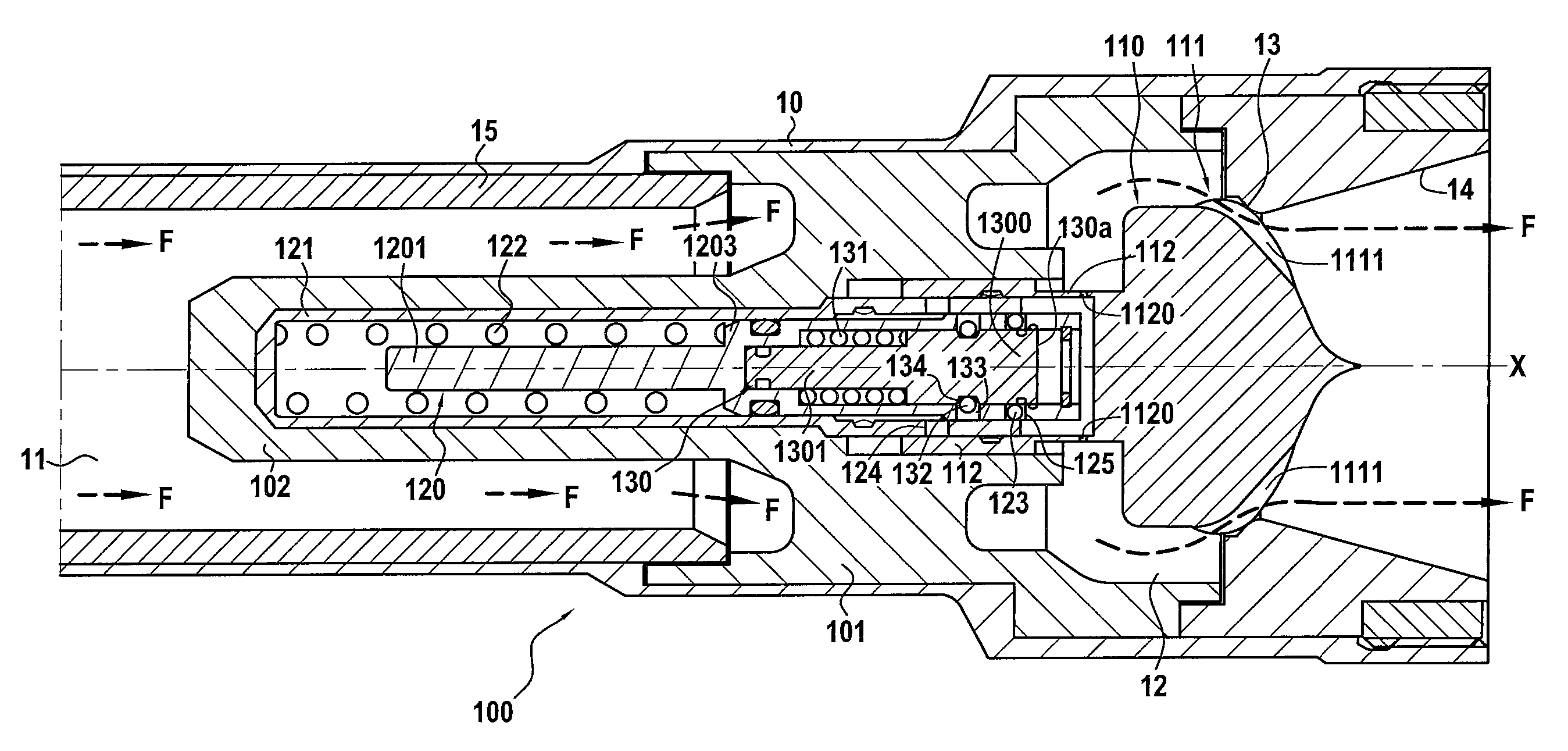
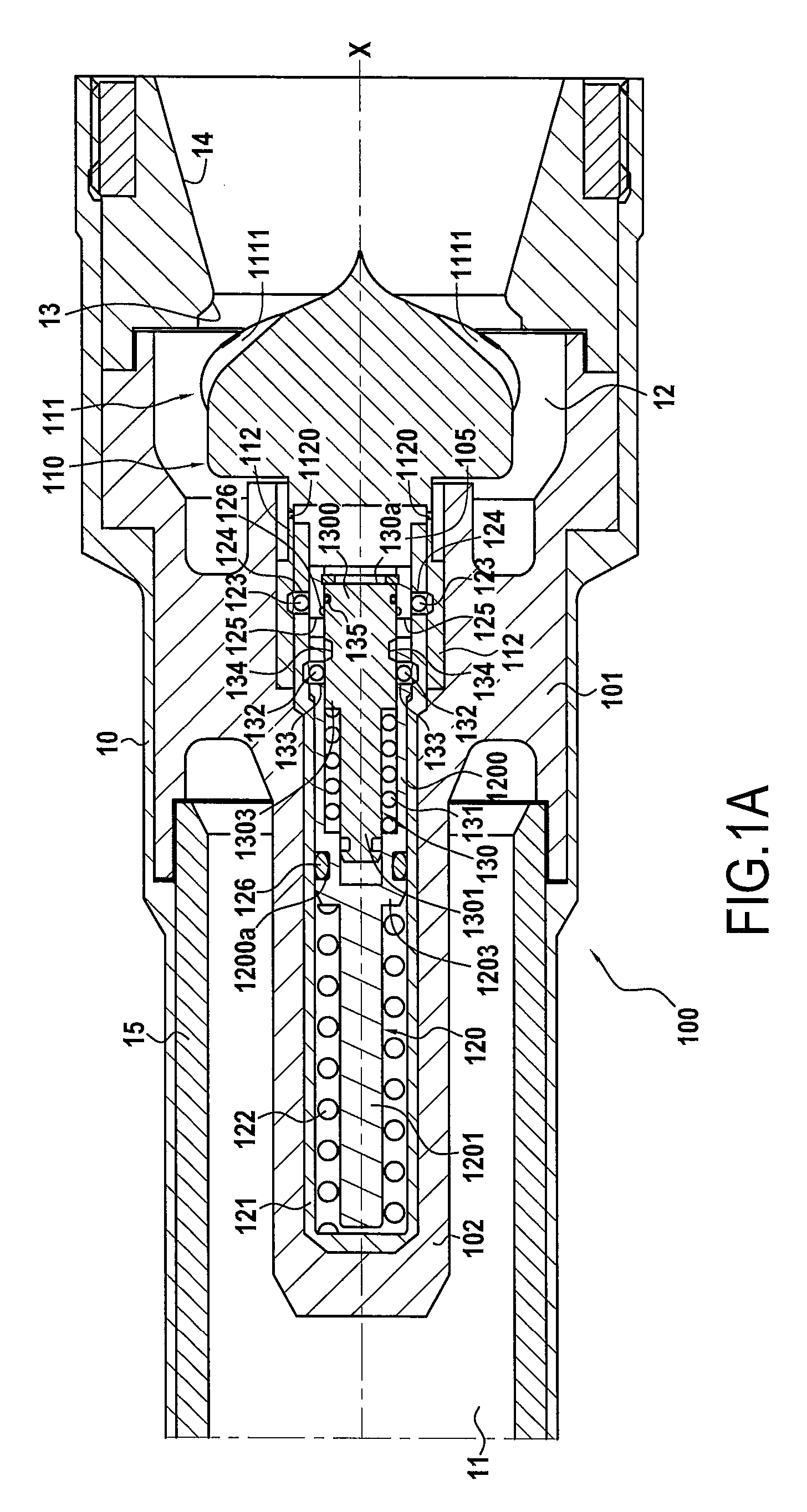
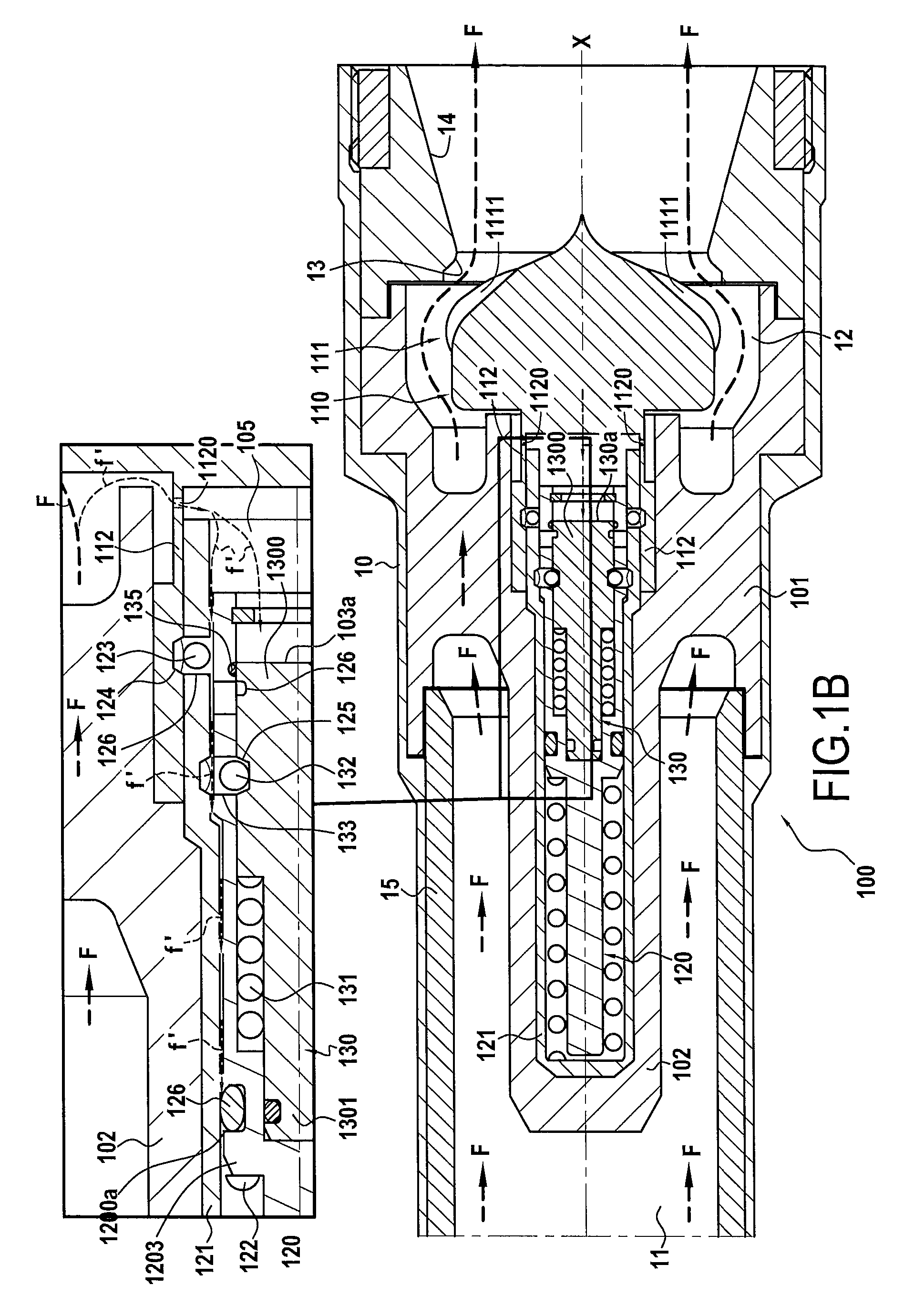
[0026]FIG. 1A is a diagrammatic longitudinal section view of the rear portion of a rocket engine comprising a shell 10 in the form of a body of revolution surrounding a combustion chamber 11 housing a block of solid propellant (not shown) at its upstream end. The chamber 11 opens through the rear end wall of the shell upstream from a nozzle 12 having a nozzle throat 13 that forms the main ejection section followed by a diverging portion 14 that is shown in part only in FIG. 1A. An inner coating 15 may be formed on the inside wall of the shell 10 to provide thermal protection and sealing.

[0027]In accordance with the invention, a modulator device 100 for modulating a gas ejection section is arranged inside the shell 10 upstream from the nozzle throat 13. In the presently-described example, the modulator device 100 is held in position by two arms 101 fastened to the inside wall of the shell 10. The arms 101 are arranged at 180° from each other, with the remainder of the circumferential...


PUM


Abstract

A modulator device for modulating a gas ejection section, includes a shutter member for partially shutting a nozzle throat, a control guide of the shutter member, a main piston, and a primer piston. The control guide is movable between a retraction position for retracting the partial shutter element relative to the nozzle throat and a shutting position in which the partial shutter element is in contact with the nozzle throat. The primer piston is movable between a rest position and a priming position for priming the main piston when the pressure in the modulator device reaches a first predetermined value. The main piston is movable between a first position for locking the control guide against movement in its retraction position, and a second position for locking the control guide when the pressure in the modulator device reaches a second predetermined value less than the first predetermined value.

Description

CROSS REFERENCE TO RELATED APPLICATIONS[0001]This application is the U.S. National Stage of PCT / FR2014 / 050485 filed Mar. 4, 2014, which in turn claims priority to French Application No. 1300515 filed Mar. 7, 2013. The contents of both applications are incorporated herein by reference in their entirety.BACKGROUND OF THE INVENTION[0002]The present invention relates to the general field of thrusters or rocket engines for delivering thrust for driving aerospace vehicles such as missiles, launchers, or indeed satellites, using the principle of propulsion by reaction or by ejecting gas. The invention relates more precisely, but not exclusively, to the fixed diverging portion nozzles fitted to solid propellant thrusters.[0003]A solid propellant thruster is mainly constituted by a shell containing a block of powder (propellant), an ignitor, and a nozzle with a fixed diverging portion. The block of powder is pierced by a channel lying on the axis of the thruster that acts as a combustion cha...

Claims


Application Information

Patent Timeline
Patent Type & Authority Patents(United States)
IPC IPC(8): F02K9/08F02K9/86F02K9/26
CPCF02K9/86F02K9/08F02K9/26
Inventor CLERMONT, MATHIEUREMIGI, ALAINLARRIEU, JEAN-MICHELMARLIN, PHILIPPE
Owner ARIANEGRP SAS
Why Eureka
Try Eureka