
Air lubrication system

a lubrication system and air technology, applied in the field of air lubrication system, can solve the problems of uneven exiting of water-air mixture from the cavity, less material for small systems, uneven water-air mixture inside the cavity, etc., and achieve the effect of efficient and stable manner

Active Publication Date: 2017-01-17
SILVERSTREAM TECH
View PDF10 Cites 3 Cited by
  • Summary
  • Abstract
  • Description
  • Claims
  • Application Information

AI Technical Summary

Benefits of technology

The compact cavity system provides a stable and efficient air lubricating layer, reducing energy consumption by up to 15% while minimizing material usage and maintaining cargo space, and is insensitive to wave motions, facilitating easier installation and operation.

Problems solved by technology

Furthermore, smaller systems require less material and are easier to handle.
Another disadvantage of a 30 m long cavity, such as known from WO 2010 / 064911, is that waves will start to form inside the cavity, whereby at the rear end of the cavity such waves will cause an uneven exiting of the water-air mixture from the cavity.
This means that the lubricating layer formed between the hull and the water flowing underneath it will be uneven and thereby less efficient.

Method used


Image

  • Air lubrication system
  • Air lubrication system
  • Air lubrication system

Examples


Embodiment Construction

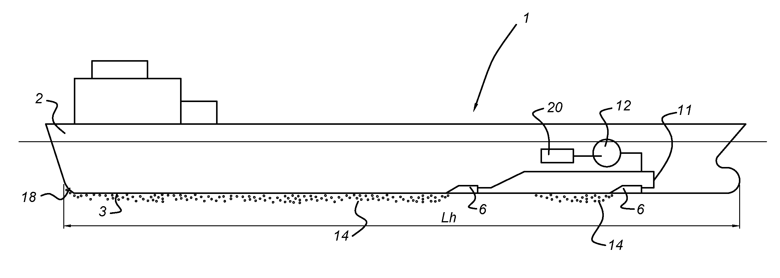
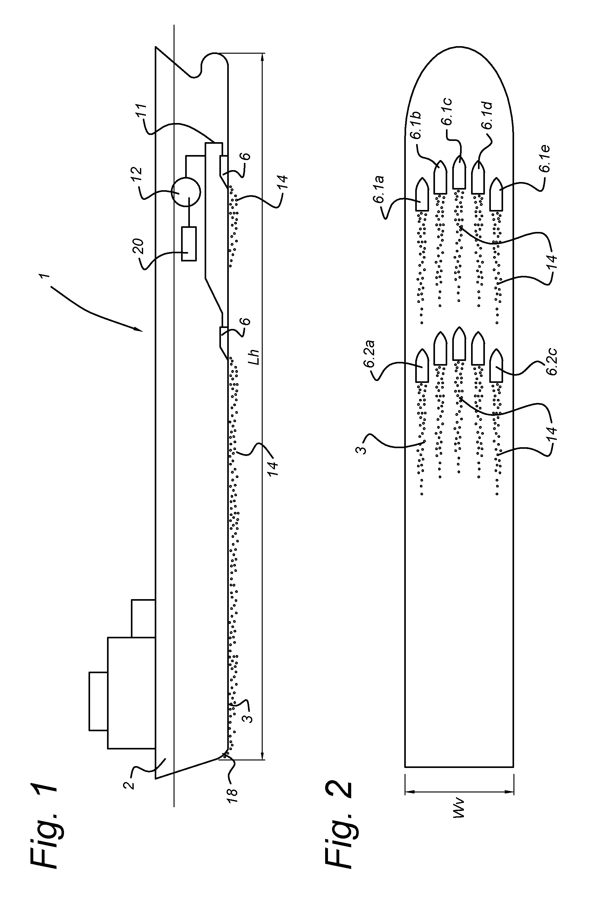
[0053]FIG. 1 shows a schematic side of a vessel 1 according to the invention having a hull 2 and a bottom surface 3. The hull2 has a length Lh of for instance between 50 m and 400 m, measured along the bottom surface 3.

[0054]As shown in FIG. 2 the bottom surface 3 of the vessel 1 comprises two rows of cavities 6, each having five cavities 6.1a to 6.1e and 6.2a to 6.2e arranged next to each another across the width Wv of the vessel. The width Wv may be between 10 and 50 m, for instance between 15 m and 20 m. The rows are shown as having a general V-shape, but the cavities could also be arranged on a straight of curved line, or in any other pattern. The number of cavities is selected according to the width Wv of the bottom surface 3. It is, however, also possible to have a single cavity in the bottom surface 3.

[0055]The cavities preferable all have the same dimensions, but they could also have different dimension, for example the cavities near the side of the vessel could have a diffe...


PUM


Abstract

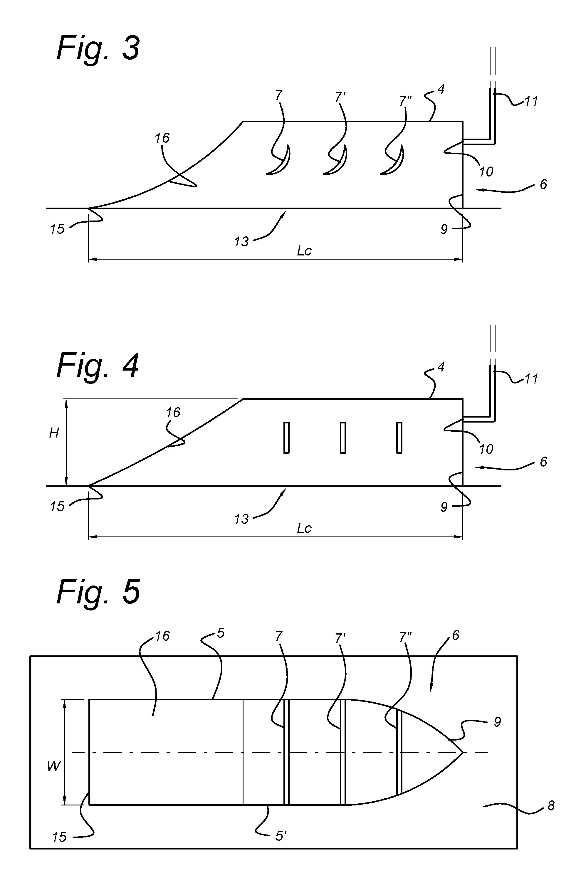
A system for providing an air lubricating layer between a substantially flat bottom (3) of a vessel (1) and the water flowing under the bottom as the vessel is moving through the water, whereby the system includes sidewalls (5,5′) and a top wall (4) defining a cavity (6) with an opening (13) situated in an interface plane that is transversal to the sidewalls (5,5′), at the level of the flat bottom (3), the opening having a front end (9) and a rear end (15) seen in the length direction of the cavity, an air inlet (10) spaced from the opening for introducing air into the cavity, whereby the length of the opening (13) of the cavity (6) is between 2 and 10 m and the distance (H) of the top wall (4) from the interface plane is between 0.2 m and 0.5 m.

Description

[0001]This application is a divisional application of U.S. application Ser. No. 14 / 379,866, filed Aug. 20, 2014, which is a 35 U.S.C. 371 national stage application of PCT / NL2013 / 050107, filed Feb. 2, 2013.FIELD OF THE INVENTION[0002]The invention relates to a system for providing an air lubricating layer between the hull of a vessel and the water flowing under the hull as the vessel is moving through the water. The invention also relates to a displacement vessel comprising such a system, to a method of operating such a system in a displacement vessel and to a method of providing such a system in a displacement vessel.BACKGROUND OF THE INVENTION[0003]WO 2010 / 064911 describes how to generate a layer of micro bubbles on the hull of a displacement vessel in order to reduce frictional drag, by means of a cavity being provided in a flat bottom area of the hull of a vessel, such that an opening of the cavity is at the flat bottom area. Air is injected into the cavity at such a rate that t...

Claims


Application Information

Patent Timeline
Patent Type & Authority Patents(United States)
IPC IPC(8): B63B1/38
CPCB63B1/38B63B2001/387Y02T70/122B63B35/00Y02T70/10
Inventor JOHANNESSON, JOHANNES
Owner SILVERSTREAM TECH
Learn More