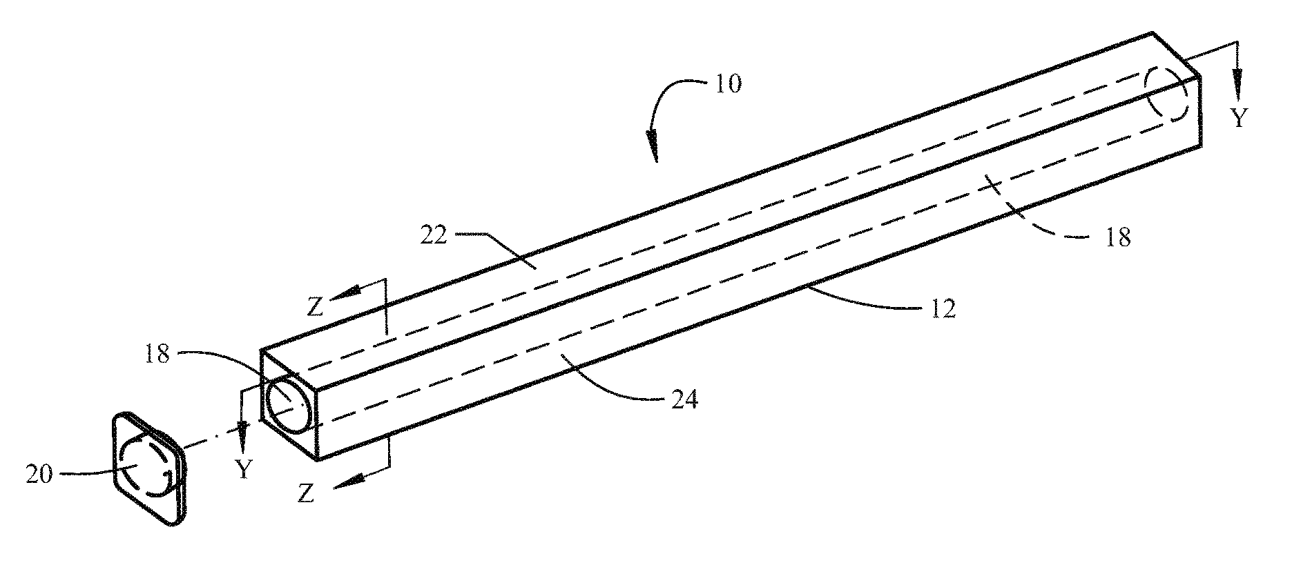
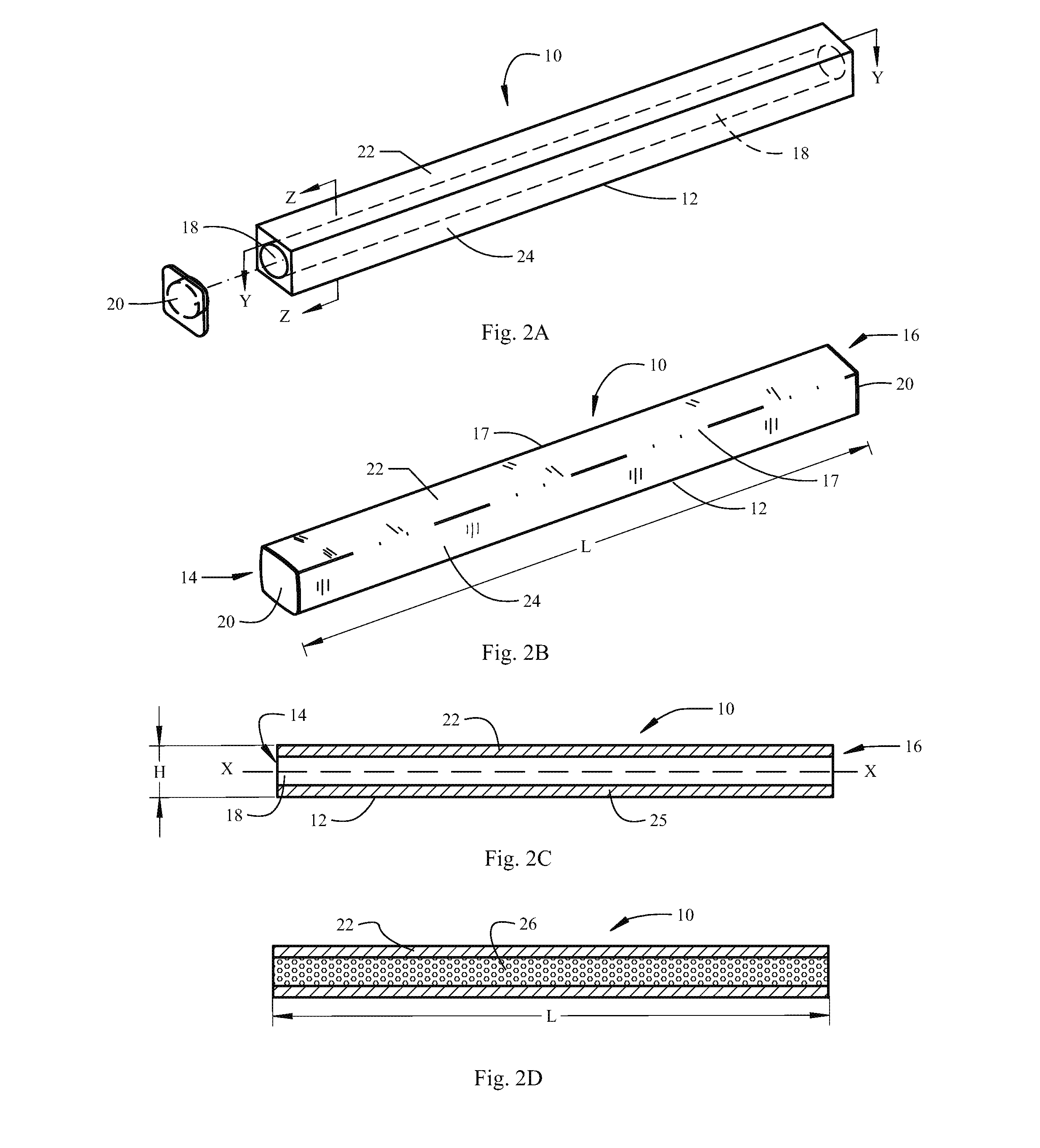
Composite structural support arm
a technology of composite structural support and cross arm, which is applied in the direction of other domestic articles, synthetic resin layered products, chemistry apparatus and processes, etc., can solve the problems of reducing the performance and service life of wood structures, increasing replacement costs, and aversion of the industry to widespread adoption of steel structures. , to achieve the effect of minimizing the size and weight of the structure and maximizing the load capacity
- Summary
- Abstract
- Description
- Claims
- Application Information
AI Technical Summary
Benefits of technology
Problems solved by technology
Method used
Image

Examples
example 1
PVC Encased Cross Arm
[0083]A beam device was manufactured by wet pultrusion of fiberglass fiber strands and resin through a square polyvinyl chloride (PVC) casing section and around a centrally-located casing pipe of PVC, as disclosed in U.S. Pat. No. 5,004,574. The wet-pultruded PVC encased device fabricated by this method achieved all structural requirements. However, centering of the inner PVC pipe was difficult to control. Additionally, the cost of manufacturing a structure according to this method and the time needed for manufacture were excessive. In addition, the quality achieved was inconsistent.
example 2
Pultruded Beam
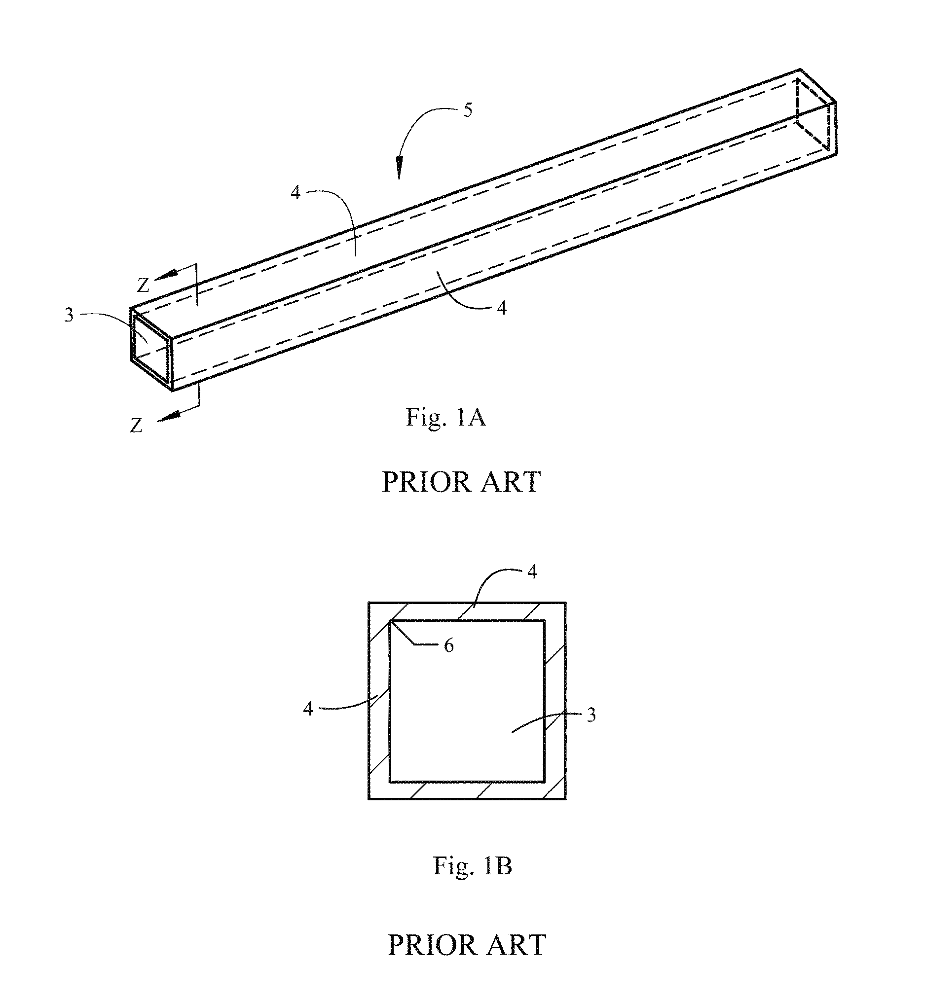
[0084]A study was carried out to compare and test the cross-sectional shape of the inner core of a prior art design and a design of the present invention. A pultruded square-shaped device with a square inner chamber (FIG. 7A) was manufactured and compared with a device having a design according to the present invention, i.e. rectangular outer surface and hollow curvilinear (i.e. circular) inner core (FIG. 7B). A stress evaluation test revealed interesting differences and surprising advantages of a structure fabricated according to a design of the present invention.
[0085]Background and Analysis of Test Results
[0086]The inertia (I) of the structure according to FIG. 7A is expressed by:
IA=(d14−d24) / 12;
For d1=3.5 in. and d2=2.75 in,
IA=7.74 in4
The area of this structure AA=d12−d22=4.68 in2.
[0087]The inertia (I) of a structure according to the invention as depicted in FIG. 7B is expressed by:
IB=(D14 / 12)−(πD24 / 64)
For D1=3.5 in. and D2=2.75 in,
IB=9.70 in4
[0088]The area of th...
example 3
Load Versus Deflection
[0102]Three tests were performed on an 8-foot cross arm of the invention to measure maximum load and maximum deflection. The results are shown graphically in FIG. 8 and in Table 3 below. The maximum load averages to 22,639 lbs-force.
[0103]
TABLE 3Load v. deflectionTest armMax load (lbs-force)Max Deflection (inches)1249275.42199063.73230843.8**Projected deflection
PUM
| Property | Measurement | Unit |
|---|---|---|
| diameter | aaaaa | aaaaa |
| diameter | aaaaa | aaaaa |
| width | aaaaa | aaaaa |
Abstract
Description
Claims
Application Information
PatSnap Eureka turns technology decisions into work you can execute. Powered by our Innovation Knowledge Graph, it runs expert workflows across engineering, life sciences, materials and intellectual property. Get your review-ready output in minutes.


