Support structure of direct fuel injection valve

a technology of direct fuel injection and support structure, which is applied in the direction of fuel injection apparatus, machine/engine, feed system, etc., can solve the problems of unstable support of the fuel injection valve, plastic deformation of the cover layer,

Active Publication Date: 2017-01-17
HITACHI ASTEMO LTD
View PDF63 Cites 5 Cited by
  • Summary
  • Abstract
  • Description
  • Claims
  • Application Information

AI Technical Summary

Benefits of technology

[0005]In the above support structure of a direct fuel injection valve, the set load applied to the resilient holding member is very high because of the necessity to withstand the high pressure of the combustion chamber of the engine. In the conventional structure, however, the rear end portion of the cover layer made of the synthetic resin is provided with the second load bearing portion which is to be supported by the resilient holding member in the axial direction, and the high set load applied to the resilient holding member causes the cover layer to undergo plastic deformation over a long period of time. The cover layer thus deformed may lower the set load of the resilient holding member and consequently make the supporting of the fuel injection valve unstable.
[0009]According to the aspect of the present invention, the valve housing made of the metal is provided with the first load bearing portion which is to be supported by the engine in the axial direction of the valve housing, the rear end portion of the fixed core is provided with the second load bearing portion which is to be supported by the resilient holding member in the axial direction, and the first and second load bearing portions are held between the engine and the resilient holding members with the forward set load applied to the resilient holding member by the fuel distribution pipe fitted to the fuel inlet tube and fixed to the engine. Thus, the valve housing and the fixed core being entirely metallic members are present between the first and second load bearing portions. Even when a high set load of the resilient holding member continuously acts on these metallic members, the metallic members are unchanged in shape and thus the set load of the resilient holding member is also unchanged. Hence, the fuel injection valve can be stably supported for a long period of time. On the other hand, the cover layer formed by molding on the coil housing and the fixed core is placed on inner sides of the first and second load bearing portions and does not receive the set load of the resilient holding member. Thus, the cover layer is free from a deformation due to the set load and thereby can secure the sealing performance on the coil hosing and the fixed core.

Problems solved by technology

In the conventional structure, however, the rear end portion of the cover layer made of the synthetic resin is provided with the second load bearing portion which is to be supported by the resilient holding member in the axial direction, and the high set load applied to the resilient holding member causes the cover layer to undergo plastic deformation over a long period of time.
The cover layer thus deformed may lower the set load of the resilient holding member and consequently make the supporting of the fuel injection valve unstable.

Method used


Image

  • Support structure of direct fuel injection valve
  • Support structure of direct fuel injection valve
  • Support structure of direct fuel injection valve

Examples


Embodiment Construction

[0014]Hereinafter, an embodiment of the present invention is described based on the accompanying drawings.

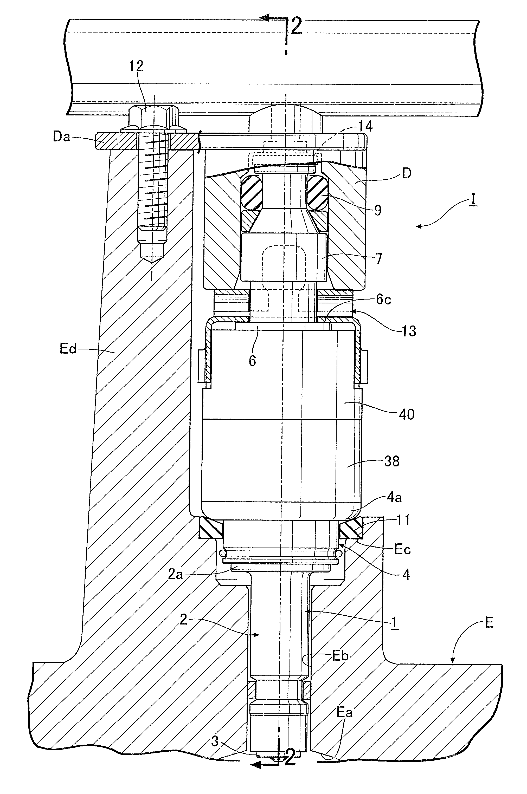
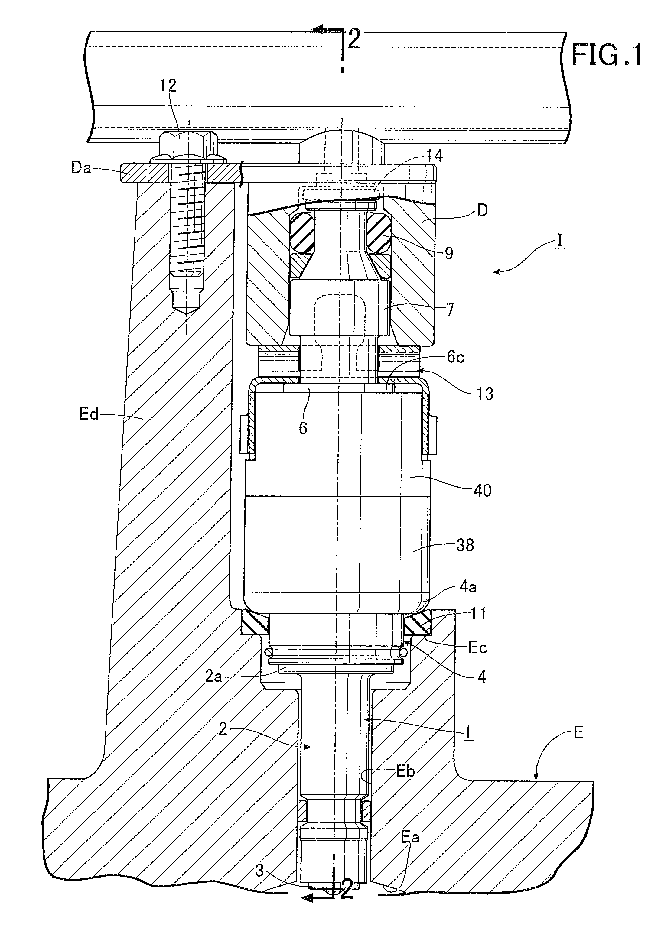
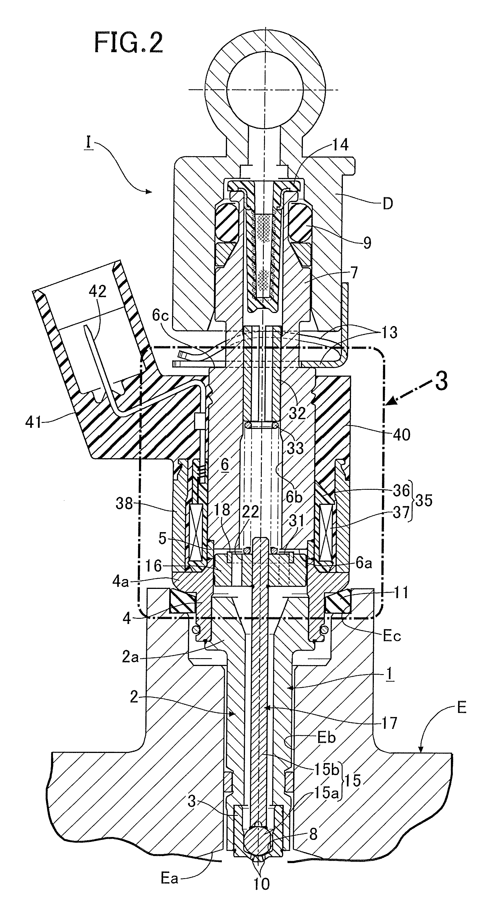
[0015]In FIGS. 1 and 2, a cylinder head E of an engine is provided with a mounting hole Eb opened to a combustion chamber Ea, and an electromagnetic fuel injection valve I is mounted in the mounting hole Eb. This fuel injection valve I is capable of injecting a fuel to the combustion chamber Ea. Here, in the fuel injection valve I, a fuel injection side is referred to as the front, whereas a fuel inlet side is referred to as the rear.

[0016]A valve housing 1 of the fuel injection valve I includes a valve housing body 2 made of a metal and formed in a hollow cylindrical shape, a valve seat member 3 formed in a bottomed cylindrical shape, and fitted and welded to an inner peripheral surface of a front end portion of the valve housing body 2, a magnetic cylindrical body 4 fitted and welded to an outer periphery of a large-diameter portion 2a at a rear end of the valve housing body 2...


PUM


Abstract

In a support structure of a direct fuel injection valve capable of supporting a fuel injection valve stably for a long period of time, a valve housing is made of a metal and is provided with a first load bearing portion which is to be supported by an engine in an axial direction of the valve housing, a rear end portion of the fixed core is provided with a second load bearing portion which is to be supported by a resilient holding member in the axial direction, and the first and second load bearing portions are held between the engine and the resilient holding members with a forward set load applied to the resilient holding member by a fuel distribution pipe fitted to a fuel inlet tube and fixed to the engine.

Description

BACKGROUND OF THE INVENTION[0001]Field of the Invention[0002]The present invention relates to an improvement of a support structure of a direct fuel injection valve comprising: a valve housing including a valve seat at a front end thereof; a fixed core provided to be connected to a rear end of the valve housing; a fuel inlet tube continued from a rear end of the fixed core; a movable core opposed to an attraction surface of a front end of the fixed core; a coil provided around an outer periphery of the fixed core; a valve body housed in the valve housing and configured to operate in cooperation with the valve seat; a coil housing having a front end bonded to the valve housing, and housing the coil therein; and a cover layer made of a synthetic resin and formed by molding to extend from the coil housing to the fixed core, in which a fuel is directly injected to a combustion chamber of an engine when the valve body is opened with the coil energized to cause the fixed core to attract t...

Claims


Application Information

Patent Timeline
Patent Type & Authority Patents(United States)
IPC IPC(8): F02M39/00F02M51/06F02M61/14
CPCF02M39/00F02M51/0671F02M61/14F02M2200/851F02M2200/855
Inventor OKAMOTO, ATSUSHIKAMAHORA, ATSUSHIMIYASHITA, JUNICHISUMISYA, NORIAKI
Owner HITACHI ASTEMO LTD
Why Eureka
Try Eureka