Method for detecting fast time constant targets using a metal detector

a metal detector and fast time constant technology, applied in the field of fast time constant target detection using a metal detector, can solve the problems of extremely rapid decay, undesirable detection of signals in metal detectors, particularly short signal components, etc., and achieve the effect of reducing the time constant and reducing the critical damped delay

Active Publication Date: 2017-01-17
MINELAB ELECTRONICS
View PDF6 Cites 2 Cited by
  • Summary
  • Abstract
  • Description
  • Claims
  • Application Information

AI Technical Summary

Benefits of technology

[0007]According to a first aspect of the present invention, there is provided a method for reducing a delay, between a transition of a transmission of a metal detector and a process of a receive signal received by a receive coil of the metal detector, due to a critically damped time constant of the receive coil, including: introducing a negative capacitance into the receive coil to reduce the critically damped time constant.
[0011]In one form, the negative capacitance generator reduces an effective parallel capacitance of the receive coil.
[0013]In one form, a feedback loop of the amplifier includes a small capacitance for improving the stability of the negative capacitance generator.

Problems solved by technology

Typically, these signals from mildly conductive soil have signal components of particularly short duration; they will decay very rapidly.
Detection of these signals is undesirable in a metal detector.
In most detectors, however, the demodulation must be delayed by more than is required to remove the effect of the signals from mildly conductive ground.
The required delay before demodulation, (or sampling), is undesirable for the detection of fast constant metal targets, because much of the decaying signal from the fast time constant targets following a transition of the transmit signal occurs during the delay, and thus most of this target signal is not added into the receive demodulation.

Method used


Image

  • Method for detecting fast time constant targets using a metal detector
  • Method for detecting fast time constant targets using a metal detector
  • Method for detecting fast time constant targets using a metal detector

Examples


Embodiment Construction

[0019]The present invention offers an alternative method over the prior art for detecting fast time constant targets using a metal detector. The method is to cancel part of the capacitance associated with the receive coil, both from its self-capacitance and the capacitance of the connecting cable, using a negative capacitance impedance generator. In practice, the critically damped time constant can be improved by a factor of about 0.5 to 0.7, e.g. a time constant of say 0.3 μs reduced to one of say 0.2 or 0.15 μs, with no signs of instability or any sort of undesirable artefacts at the time of writing.

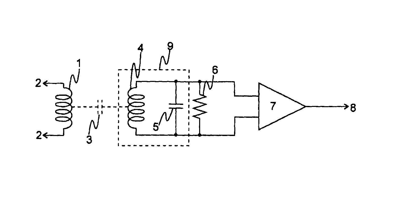
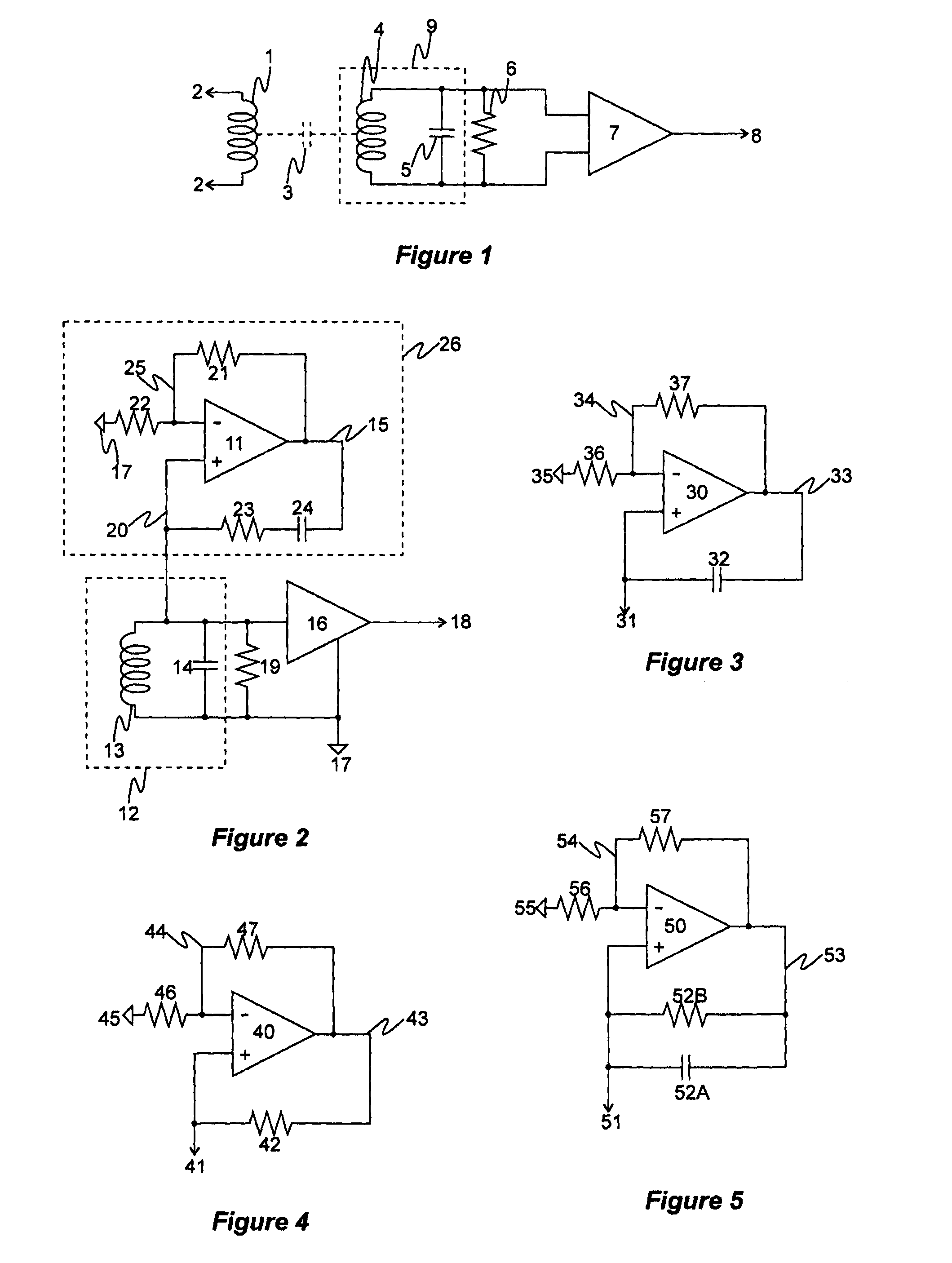
[0020]FIG. 1 depicts a simple circuit of a metal detector, including a transmit winding 1 and a receive winding 4, to describe the problem addressed by the present invention.

[0021]The transmit winding 1 is connected 2 to transmit electronics (not shown) for receiving a transmit signal. A sudden transition in the transmit winding 1 can be capacitively coupled to the receive winding 4 th...


PUM


Abstract

A method for reducing a delay, between a transition of a transmission of a metal detector and a process of a receive signal received by a receive coil of the metal detector, due to a critically damped time constant of the receive coil, including: introducing a negative capacitance into the receive coil to reduce the critically damped time constant.

Description

TECHNICAL FIELD[0001]This invention relates to a method for detecting fast time constant targets using a metal detector.INCORPORATION BY REFERENCE[0002]This patent application claims priority from:[0003]Australian Provisional Patent Application No 2012900870 titled “A Circuit of a Metal Detector” filed 6 Mar. 2012.[0004]The entire content of this application is hereby incorporated by reference.BACKGROUND ART[0005]Time domain metal detectors usually synchronously demodulate (or sample) a receive signal from a receive coil commencing after a short delay following a voltage transition of a transmit signal, for example, after the back emf of a pulse induction (PI) transmit pulse, or after a switch from a high voltage (e.g. 200V) to a low-voltage (e.g. 5V) or to zero voltage. The short delay is to avoid the processing electronics from demodulating potential spurious interfering signals (unwanted signals) from mildly conductive soils. Typically, these signals from mildly conductive soil h...

Claims


Application Information

Patent Timeline
Patent Type & Authority Patents(United States)
IPC IPC(8): G01R35/00G01V3/10G01R27/26
CPCG01R35/00G01R27/2611G01V3/10
Inventor CANDY, BRUCE HALCRO
Owner MINELAB ELECTRONICS
Why Eureka
Try Eureka