
Antenna mount

Inactive Publication Date: 2017-01-17
WALLMAN KENNETH
View PDF4 Cites 5 Cited by
  • Summary
  • Abstract
  • Description
  • Claims
  • Application Information

AI Technical Summary

Benefits of technology

The invention is a way to attach an antenna to a building by adding a section to the roof rafters or walls. This makes the antenna unobtrusive and can be done before the building is sold to ensure a consistent appearance. The technical effect is to provide a way to attach antennas to buildings in a simple and aesthetically pleasing way.

Problems solved by technology

They all look fairly ugly and detract from the beauty of the building design.
Eventually, each house in an area has different antennas, sprouting at different locations and angles on each house, which renders the area less beautiful.

Method used


Image

  • Antenna mount
  • Antenna mount
  • Antenna mount

Examples


Embodiment Construction

[0031]While the present invention is described herein with reference to illustrative embodiments for particular applications, it should be understood that the invention is not limited thereto. Those having ordinary skill in the art and access to the teachings provided herein will recognize additional modifications, applications, and embodiments within the scope thereof and additional fields in which the present invention would be of significant utility.

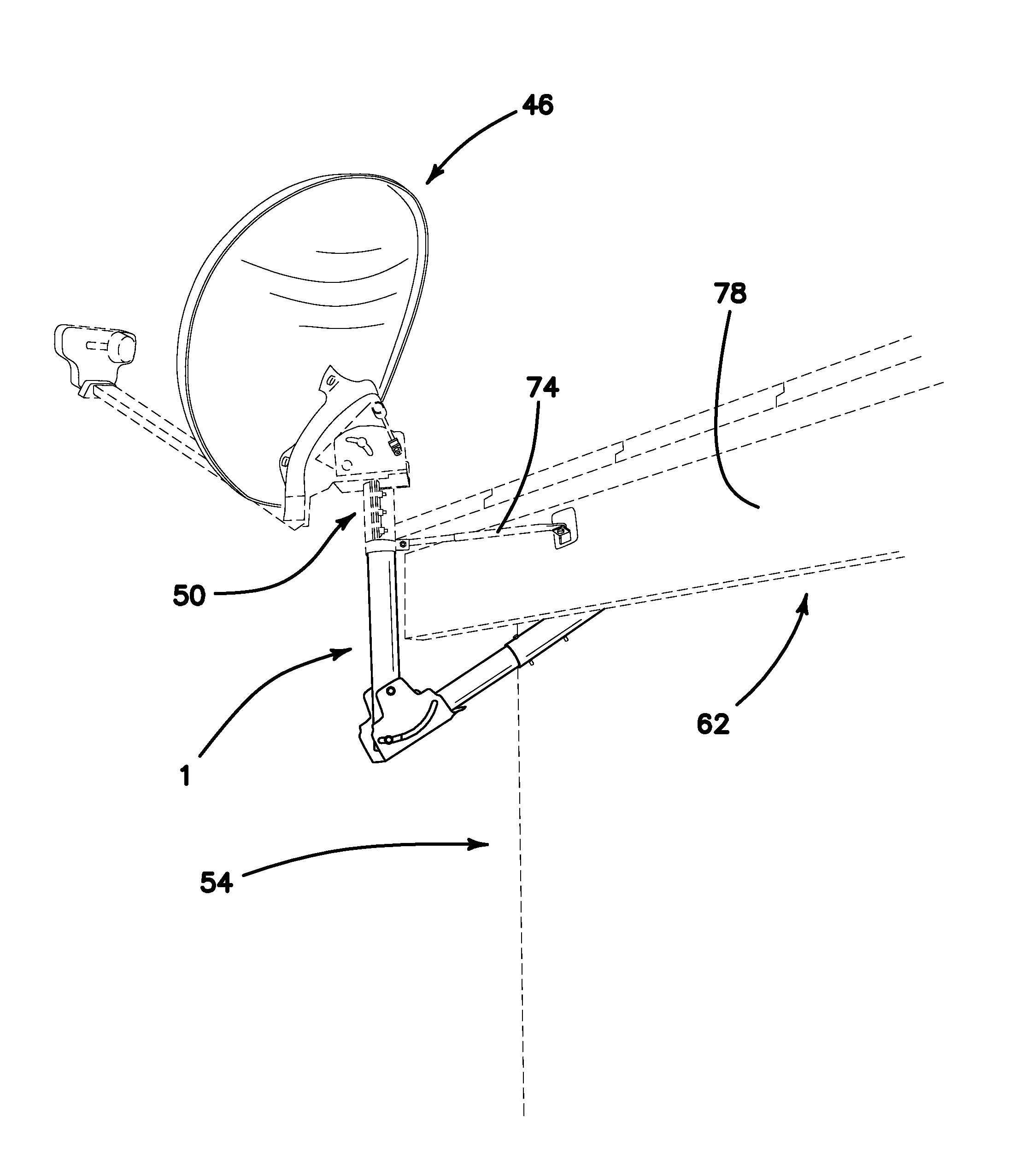
[0032]FIGS. 7, 8, 9, 10 and 11 show the main components of this invention 1:

[0033]a base plate 10 designed to be attached under a roof rafter or a to a stud 66 of an exterior wall;

[0034]a first leg 14 attached to the base plate 10 by a first attachment 18;

[0035]a second leg 22 attached to the first leg 14 by a second attachment 26;

[0036]a third leg 30 attached to the second leg 22 by a third attachment 36; and

[0037]a fourth leg 34 attached to the third leg 30 by a fourth attachment 38.

[0038]The free end 42 of the fourth leg 34 is desi...


PUM


Abstract

An antenna mount comprising: a building attachment section including an accessible end; and an antenna support section including a free end and a second accessible end. The accessible end and the second accessible are attached to each other by a joint. The free end is designed so that the antenna can be attached to it. The invention is designed so that the free end is vertical and the antenna is situated far away enough from the building so that it will clear the building when rotated 360°.

Description

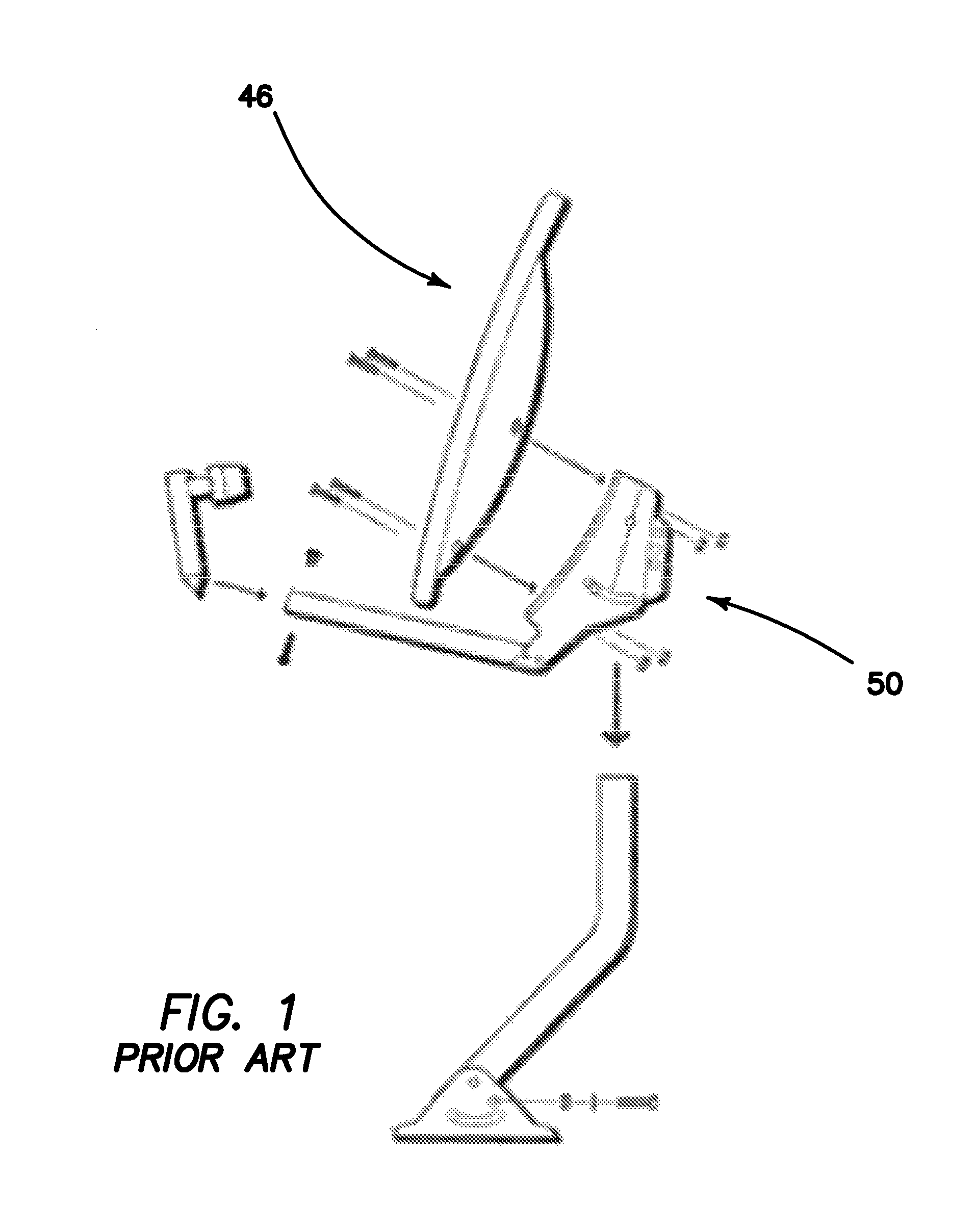
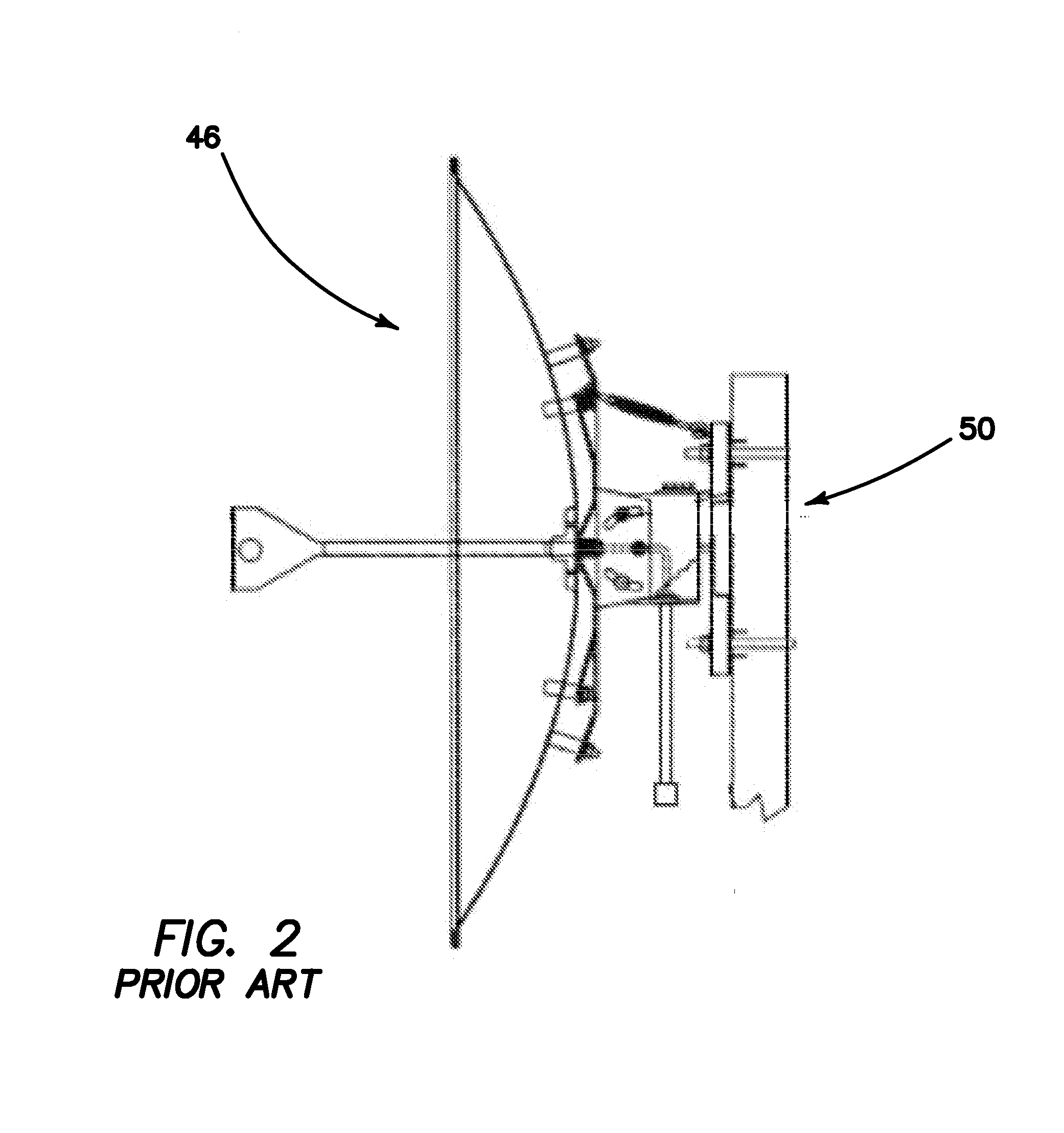
BACKGROUND OF THE INVENTION[0001](1) Field of the Invention[0002]The present invention relates to the field of building construction and more particularly to the field of mounting antennas on buildings.[0003](2) Description of the Related Art[0004]We are used to seeing radio and TV antennas on buildings throughout the world. We used to see Yagi, log-periodic, loop and similar antennas. With the advent of HDTV and satellite television, we are now seeing dish antennas. They all look fairly ugly and detract from the beauty of the building design. This is particularly true in residential housing areas. In such areas, each individual homeowner is free to select his own TV service provider. If service using an antenna is selected by the homeowner, a technician installs the antenna where he determines the best signal can be received. It may be the roof or a wall. Each service has a preferred antenna design and support structure. Examples are shown on FIGS. 1-6. Eventually, each house in an...

Claims


Application Information

Patent Timeline
IPC IPC(8): A47G29/02H01Q1/12F16C11/04
CPCH01Q1/1207H01Q1/1221F16C11/04H01Q19/13F16C11/103F16C2380/00
Inventor WALLMAN, KENNETH
Owner WALLMAN KENNETH
Learn More