Connector socket

a technology of connecting sockets and connectors, which is applied in the direction of coupling devices, two-part coupling devices, electrical apparatus, etc., can solve the problems of unstable data transmission, unstable structure of upper lower row of contact terminals within the insulating base, and complicated procedure. , to achieve the effect of firm positioning, simple structure and easy manufacturing

Inactive Publication Date: 2017-01-17
SHENZHEN LITKCONN TECH
View PDF2 Cites 5 Cited by
  • Summary
  • Abstract
  • Description
  • Claims
  • Application Information

AI Technical Summary

Benefits of technology

[0004]Accordingly, in view of the deficiencies of the prior art, a main objective of the present invention is to provide a connector socket. The connector socket provided by the present invention is simple in structure, easy to manufacture, and firm in positioning between assembly components, and the technical solution thereof is widely applied to connector sockets of various styles and models.
[0014]As a preferred solution, the terminal ports are convexly provided thereon with limiting lugs for facilitating the firm positioning of the terminal ports and the insulating body.
[0015]Compared with the prior art, the present invention has apparent advantages and beneficial effects. Specifically, it can be seen from the above technical solution that the structure design of the shielding shell, the insulating body, the two baffles, the two rows of contact terminals and the spacer and the assembly relationship thereof allow the positioning between assembly components to be quite firm; particularly, the positioning between the upper and lower terminal groups is more accurate and firm, so that it is advantageous for the improvement of the contact performance of terminals and the stable signal transmission is ensured; moreover, each component is simple in structure and easy to manufacture, and the technical solution of the present invention is widely applied to connector sockets of various styles and models.

Problems solved by technology

Accordingly, new problems appear: interference of signal is caused between the upper row of contact terminals and the lower row of contact terminals, and it is likely to result in unstable data transmission as the conventional shielding structure design is unable to provide for good shielding effect; and, the structure for assembling the upper row of contact terminals and the lower row of contact terminals within an insulating base is also unstable or complicated in procedure.

Method used


Image

  • Connector socket
  • Connector socket
  • Connector socket

Examples


Embodiment Construction

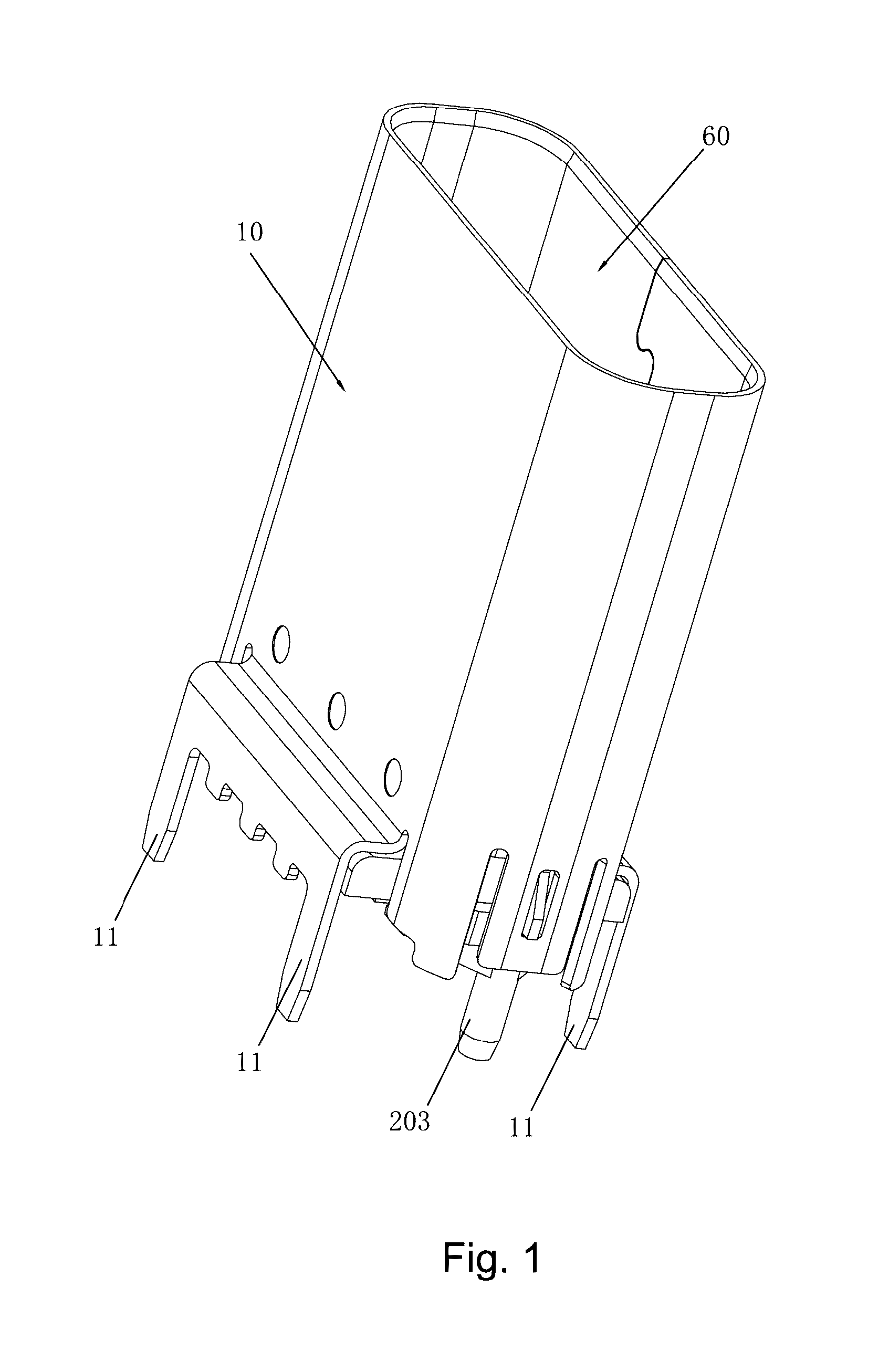
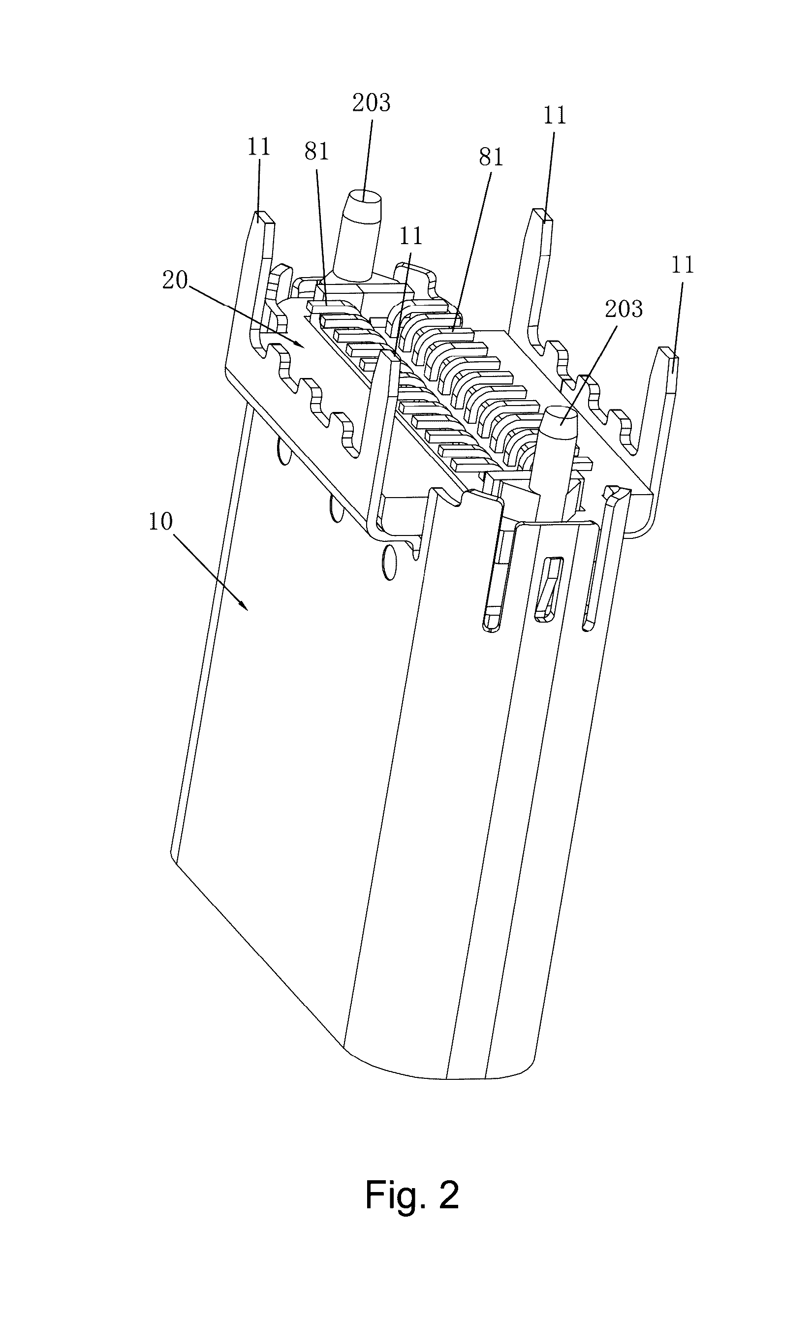
[0032]Referring to FIG. 1 to FIG. 15, the specific structures of multiple embodiments of the present invention are shown. The technical solution of the present invention is widely applied to connector sockets of various styles and models. Here, the following three embodiments are selected for description.

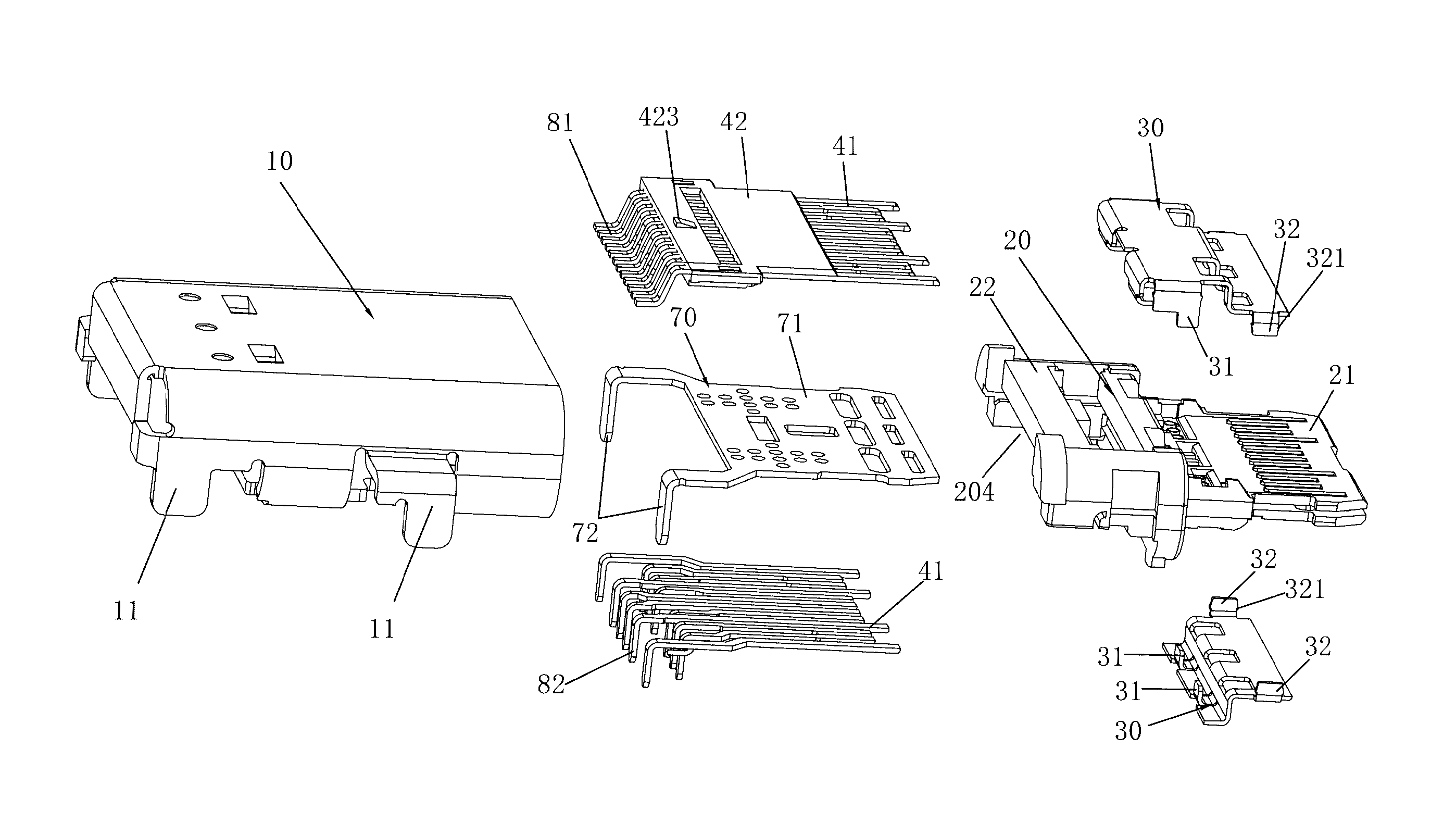
[0033]As shown in FIG. 1 to FIG. 5, one embodiment of an vertical connector socket is shown, including a shielding shell 10, an insulating body 20 and two baffles 30 disposed on two opposite sides of the insulating body 20, and further including two rows of contact terminals 41 and a spacer 50 all embedded into the insulating body 20.

[0034]The insulating body 20 includes a base 21 and a tongue plate 22 connected to a front end of the base 21, the two rows of contact terminals 41 being exposed from two opposite sides of the tongue plate 22, respectively, the two baffles 30 being disposed to correspond to the sides where the two rows of contact terminals 41 are located, respectively. ...


PUM


Abstract

A connector socket comprises a shielding shell, an insulating body and two baffles disposed on two opposite sides of the insulating body, and further comprises two rows of contact terminals and a spacer all embedded into the insulating body, the insulating body comprises a base and a tongue plate connected to a front end of the base, the two rows of contact terminals are exposed from two opposite sides of the tongue plate, respectively, the two baffles are disposed to correspond to the sides where the two rows of contact terminals are located, respectively; the spacer is located between the two rows of contact terminals so as to isolate the two rows of contact terminals from one another; a plurality of positioning holes for reinforcing the firmness of connection between the spacer and the insulating body are formed on the spacer.

Description

FIELD OF THE INVENTION[0001]The present invention relates to the technical field of electric connectors, in particular to a connector socket.BACKGROUND OF THE INVENTION[0002]At present, connectors have been widely applied in electronic products for data transmission, charge, video transmission and other functions. With the development demand and trend of light and thin electronic products (for example, various ultra-thin tablets, mobile phones, two-in-one boxes, other special mobile devices, etc.), connectors are becoming lighter and thinner in order to conform to the corresponding size of electronic products. As the size of connectors becomes smaller, the size of corresponding structural components is limited and the distance between an upper row of contact terminals and a lower row of contact terminals becomes smaller too. Accordingly, new problems appear: interference of signal is caused between the upper row of contact terminals and the lower row of contact terminals, and it is ...

Claims


Application Information

Patent Timeline
Patent Type & Authority Patents(United States)
IPC IPC(8): H01R13/6581H01R24/60H01R13/405H01R107/00
CPCH01R13/6581H01R13/405H01R24/60H01R2107/00
Inventor DENG, HUILUN
Owner SHENZHEN LITKCONN TECH
Why Eureka
Try Eureka