Excavation tool

a technology of excavating tool and cutting edge, which is applied in the direction of earth drilling, earthwork drilling, construction, etc., can solve the problems of uneven reducing excavation efficiency, and uniform wear and abrasion of the cutting edge portion of the excavation tip, so as to reduce the excavation cost per unit depth, improve the tool life, and uniform wear of the cutting edge portion

Active Publication Date: 2017-01-24
MMC RYOTEC CORP
View PDF50 Cites 6 Cited by
  • Summary
  • Abstract
  • Description
  • Claims
  • Application Information

AI Technical Summary

Benefits of technology

[0037]As described above, according to the present invention, in the excavation tip which is attached so as to be rotatable around the central axis of the embedding portion during the excavation, and is locked so as not to slip toward the distal end side in the direction of the central axis, it is possible to achieve uniform wear of the cutting edge portion without causing the excavation tip to fall therefrom. Even under conditions where the cutting edge portion is seriously worn due to the hard ground or rock, it is not necessary to regrind the cutting edge portion by preventing the uneven wear such as the asymmetrical wear. Therefore, it is possible to improve tool life and reduce the excavation cost per unit depth of the excavation pit by maintaining the excavation performance and excavation efficiency of an excavation tip over a longer period.

Problems solved by technology

Correspondingly, wear and abrasion of the cutting edge portion progressively occur.
Therefore, the sharpness of the cutting edge is impaired, thereby the excavation efficiency decreases.
Furthermore, if the wear of the excavation tip progressively occurs until the diameter of the excavation pit becomes an acceptable diameter or smaller, the tool life of the excavation tool is finished.
However, the wear and the abrasion of the cutting edge portion of the excavation tip are not uniform.
For example, among the multiple excavation tips embedded in the distal end portion of the tool body, especially in the excavation tip embedded in a gauge portion of an outer peripheral side of the distal end portion, the wear and the abrasion become significant on a surface facing the outer peripheral side.
Since asymmetrical wear occurs, an excavation performance is likely to be impaired, thereby causing decreased excavation efficiency.
This wear of the excavation tip in the gauge portion is relevant to a decrease in the diameter of the excavation pit, and thereby seriously affects tool life.
Then, this uneven wear of the cutting edge portion of the excavation tip is more significant under conditions where the cutting edge portion is seriously worn due to the hard ground or rock.
As a result, the tool life is shortened and the cost for excavation increases.
In addition, it also takes money and time to regrind the cutting edge portion of the excavation tip in order to recover the excavation performance.
Furthermore, if the tool life of the excavation tool is finished before the excavation pit is excavated to reach a desired depth, it takes time, effort and money to replace the tool body.
In addition, if the wear and the abrasion of the cutting edge portion progressively occur and yet the excavation is continued while the excavation performance remains impaired, the wear or damage may occur in the tool body, and an overload is imposed on the excavator.

Method used


Image

  • Excavation tool
  • Excavation tool
  • Excavation tool

Examples


Embodiment Construction

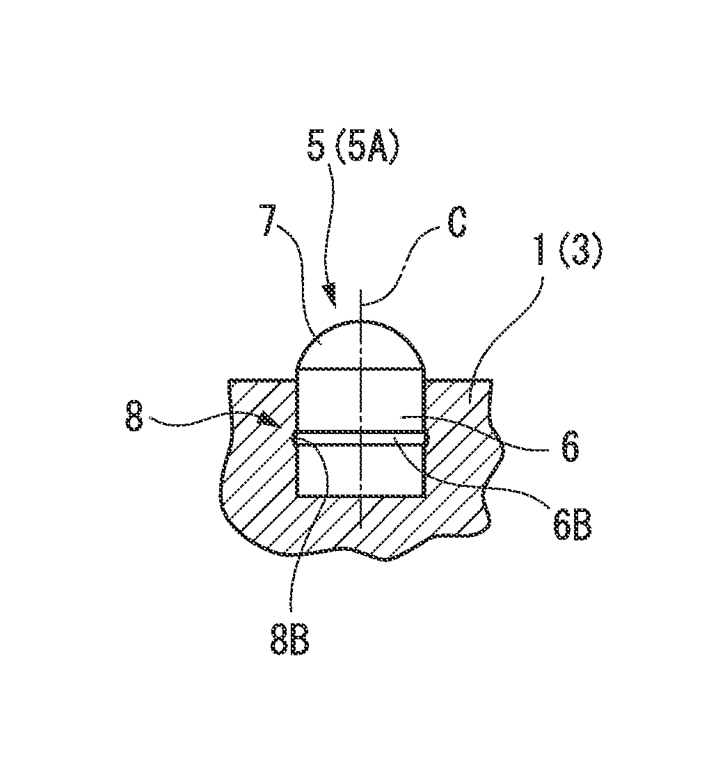
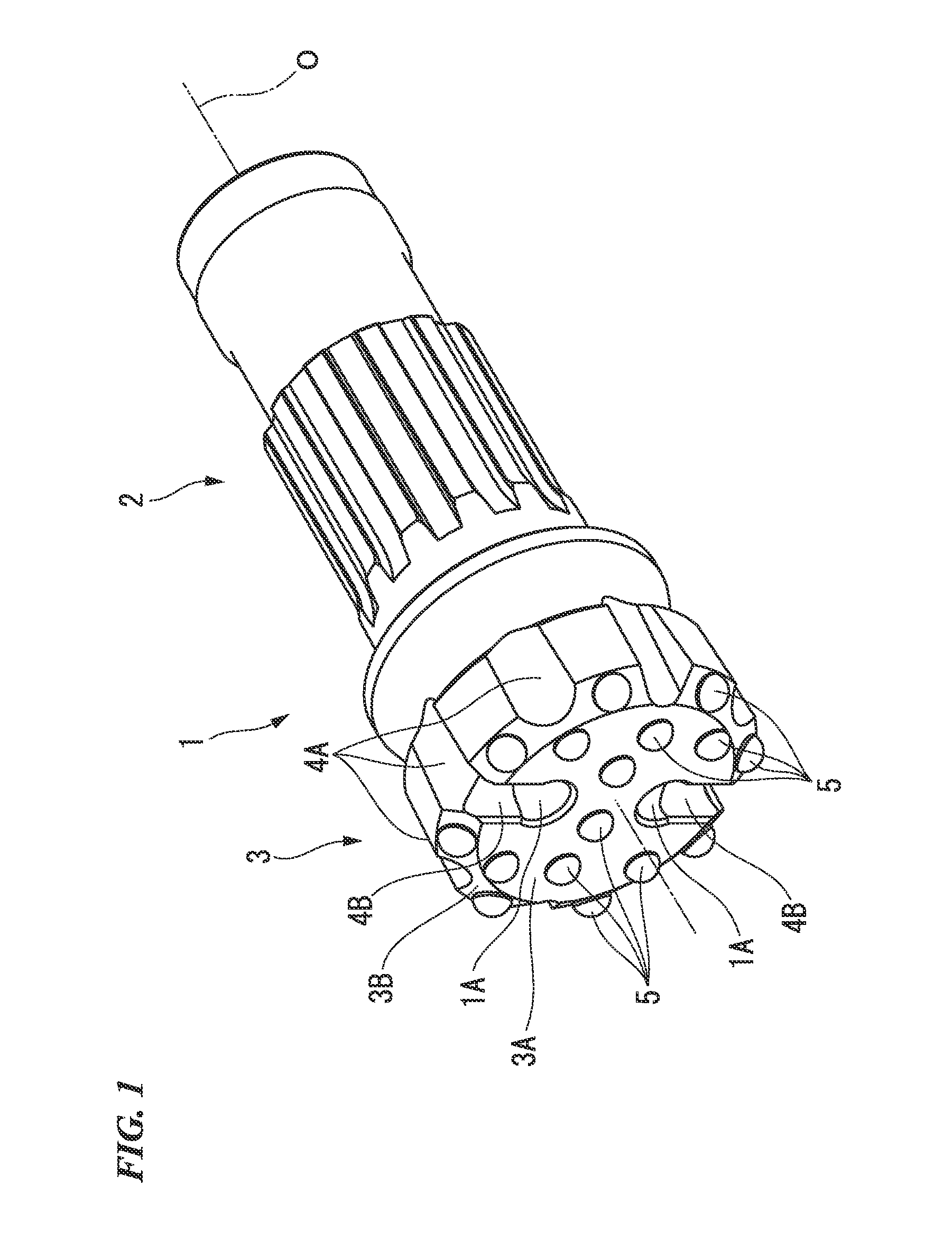
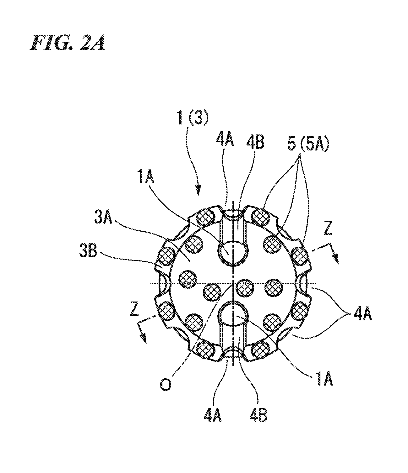
[0066]FIGS. 1 to 5B respectively illustrate first to fourth embodiments of the present invention. In these embodiments, a tool body 1 is formed of steel. As illustrated in FIG. 1, a distal end thereof (left side portion in FIG. 1, lower side portion in each B view of FIGS. 2A to 5B) has a large diameter. An outer diameter thereof is gradually decreased as the tool body 1 faces a rear end side (right side portion in FIG. 1, upper side portion in each B view of FIGS. 2A to 5B). The tool body 1 has a substantially multi-stage cylindrical shape centered on an axis line O.

[0067]A rear end portion of the tool body 1 serves as a shank portion 2. The shank portion 2 is attached to a down-the-hole hammer (not illustrated). In this manner, the tool body 1 receives a striking force to a distal end side in a direction of the axis line O from the down-the-hole hammer. In addition, an excavator is connected to the rear end of the down-the-hole hammer via an excavation rod (not illustrated). The t...


PUM


Abstract

In an excavation tool of the present invention, an embedding hole is drilled in a distal end portion of a tool body which is rotated about an axis line O and is moved forward to a distal end side in a direction of the axis line O. In the embedding hole, an excavation tip in which an embedding portion having an outer cylindrical shape is formed integrally with a cutting edge portion inserts the embedding portion into the embedding hole and causes the cutting edge portion to protrude from the embedding hole. In this manner, the excavation tip is rotatable around a central axis C of the embedding portion during excavation, and is attached thereto by being locked so as not to slip toward a distal end side of the embedding portion 6 in a direction of the central axis C.

Description

TECHNICAL FIELD[0001]The present invention relates to an excavation tool in which an embedding hole is drilled in a distal end portion of a tool body which is rotated about an axis line and is moved forward to a distal end side in a direction of the axis line, and in which an excavation tip made of a hard material is embedded in the embedding hole so that a cutting edge portion of the distal end thereof protrudes therefrom.[0002]Priority is claimed on Japanese Patent Application No. 2011-262526, filed Nov. 30, 2011 and Japanese Patent Application No. 2012-251357, filed Nov. 15, 2012, the contents of which are incorporated herein by reference.BACKGROUND ART[0003]For example, as disclosed in PTLs 1 and 2, a known excavation tool includes those which form an excavation pit in the ground or in rock in the following manner. A steel tool body, to a distal end of which multiple excavation tips made of sintered alloys such as ultra-hard metal alloys are attached, is attached to a distal end...

Claims


Application Information

Patent Timeline
Patent Type & Authority Patents(United States)
IPC IPC(8): E21B10/43E21B10/56E21B10/573E21B10/62E21B10/633
CPCE21B10/43E21B10/633E21B10/54E21B10/38
Inventor HIWASA, YONEOHISADA, MASAYANAKAMURA, KAZUYOSHI
Owner MMC RYOTEC CORP
Why Eureka
Try Eureka