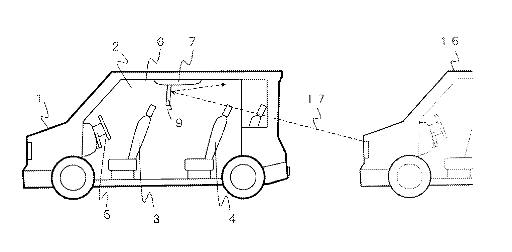

Vehicle-mounted electronic device

a vehicle-mounted electronic device and vehicle-mounted technology, applied in the field of vehicle-mounted electronic devices, can solve the problems of extremely difficult to see display units, and achieve the effects of reducing the influence of the illumination of the following vehicle, reducing the influence of the following vehicle illumination, and facilitating the use environment of the vehicle-mounted electronic devi

Active Publication Date: 2017-01-24
PANASONIC INTELLECTUAL PROPERTY MANAGEMENT CO LTD
View PDF35 Cites 0 Cited by
  • Summary
  • Abstract
  • Description
  • Claims
  • Application Information

AI Technical Summary

Benefits of technology

[0008]The vehicle-mounted electronic device according to the present invention includes a main body case to be attached to a ceiling surface of a vehicle, a display unit that is attached to the main body case to be openable downward and closable, a drive unit that drives the display unit to open and close, and a control unit that is connected to the drive unit, and is configured such that a sensor that detects illumination from a following vehicle is provided in at least one of the display unit and the main body case, and the control unit rotates the display unit by means of the drive unit, when the sensor detects illumination from a following vehicle. Therefore, the influence by illumination from a following vehicle can be reduced.
[0009]When the display unit of the vehicle-mounted electronic device is attached to the main body case attached to the ceiling surface of a vehicle to be openable downward and closable, the display unit extremely easily receives the influence by the illumination of a following vehicle.
[0010]Therefore, in the present invention, the sensor that detects illumination from the following vehicle is provided in at least one of the display unit and the main body case. The control unit rotates the display unit by means of the drive unit when illumination from the following vehicle is detected by the sensor. By adopting the configuration like this, illumination from the following vehicle does not reflect on the display unit toward a viewer. As a result, the influence by the illumination of the following vehicle is reduced, and the usage environment of the vehicle-mounted electronic device can be made comfortable.

Problems solved by technology

For example, vehicle-mounted electronic devices such as a car navigation device and a television receiver are often attached to the vicinities of front panels of vehicle interiors, and when the vehicle-mounted electronic devices are used in places like these, the display units become extremely difficult to see, depending on the incidence state of sunlight.

Method used


Image

  • Vehicle-mounted electronic device
  • Vehicle-mounted electronic device
  • Vehicle-mounted electronic device

Examples


embodiment 1

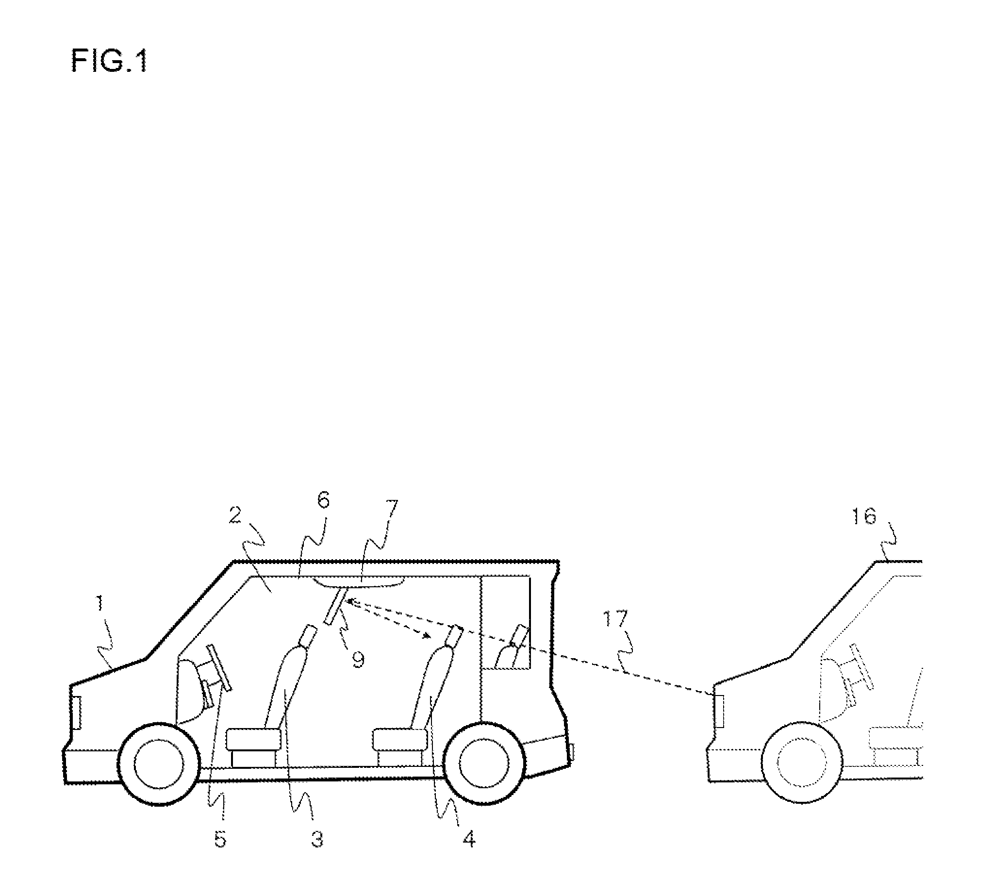
[0018]FIG. 1 is a view showing a vehicle loaded with a vehicle-mounted electronic device of one embodiment of the present invention. In the drawing, reference sign 1 designates a vehicle loaded with the vehicle-mounted electronic device according to the present invention, a front seat 3 is disposed at the front of a vehicle interior 2, and a rear seat 4 is disposed at the rear.

[0019]Further, a steering wheel 5 is disposed in front of the front seat 3 in the vehicle interior 2, and the vehicle-mounted electronic device 7 including a display unit 9 is attached to a part between the front seat 3 and the rear seat 4, of a ceiling surface 6 of the vehicle interior 2.

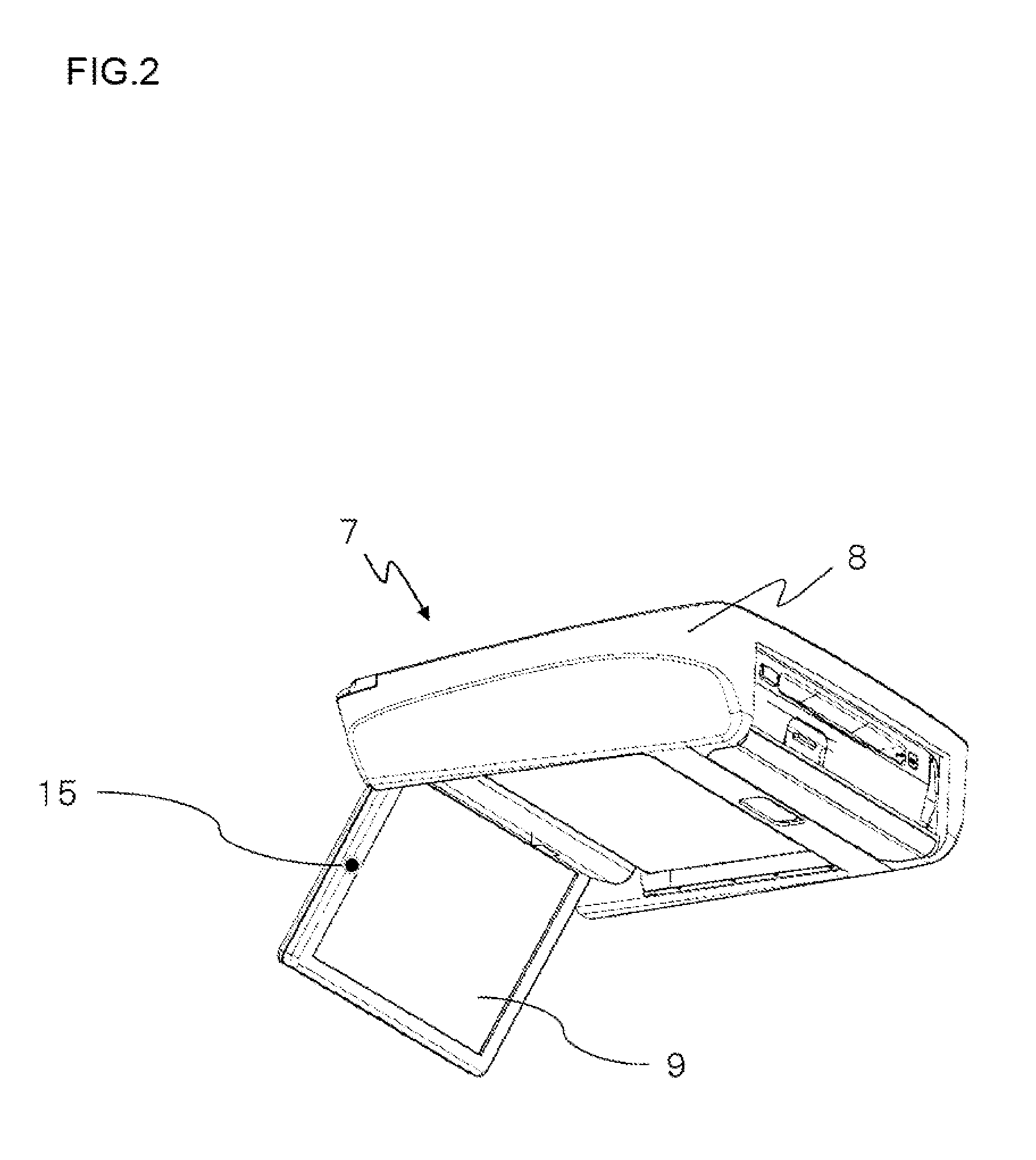
[0020]FIG. 2 is a perspective view of the vehicle-mounted electronic device 7, and FIG. 3 is a control block diagram of the vehicle-mounted electronic device 7.

[0021]As shown in FIG. 2, the vehicle-mounted electronic device 7 includes a main body case 8 to be attached to the ceiling surface 6, and the display unit 9 that is a...


PUM


Abstract

A vehicle-mounted electronic device according to the present invention is provided with a sensor 15 that detects illumination 17 from a following vehicle 16, in at least one of a display unit 9 and a main body case 7, and is configured such that a control unit 11 rotates the display unit 9 by means of a drive unit 10 when the sensor 15 detects the illumination 17 from the following vehicle 16. Thereby, the illumination 17 from the following vehicle 16 does not reflect on the display unit 9 toward a viewer, as a result of which, the influence by illumination from the following vehicle 16 can be reduced.

Description

TECHNICAL FIELD[0001]The present invention relates to a vehicle-mounted electronic device to be attached to a ceiling surface of a vehicle.BACKGROUND ART[0002]For example, vehicle-mounted electronic devices such as a car navigation device and a television receiver are often attached to the vicinities of front panels of vehicle interiors, and when the vehicle-mounted electronic devices are used in places like these, the display units become extremely difficult to see, depending on the incidence state of sunlight.[0003]Consequently, an electronic device that stores the influence of sunlight of each season, and adjusts illuminance or the like of the display unit has been proposed (for example, Patent Literature 1 as follows).CITATION LISTPatent LiteraturePatent Literature 1: Japanese Patent Laid-Open No. 09-265271SUMMARY OF INVENTIONTechnical Problem[0004]The above described conventional example has an object thereof limited to reduction in difficulty to see the display unit due to sun...

Claims


Application Information

Patent Timeline
Patent Type & Authority Patents(United States)
IPC IPC(8): H04N7/18H04N9/47H04N5/655G01C21/26B60R11/02B60R11/04B60R11/00
CPCH04N5/655B60R11/0235B60R11/04G01C21/265B60R2011/0028B60R2011/0082B60R2011/0085B60R2011/0276
Inventor YAMADA, TOMOHIRO
Owner PANASONIC INTELLECTUAL PROPERTY MANAGEMENT CO LTD
Learn More